GSM/GPRS Module Series
M66 Hardware Design
M66_Hardware_Design Confidential / Released 14 / 80
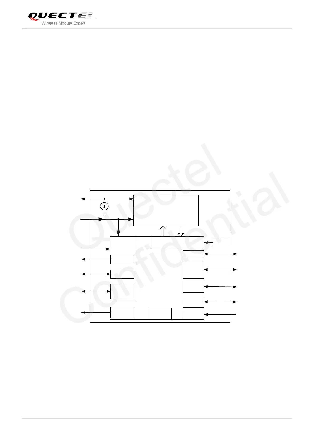
2.3. Functional Diagram
The following figure shows a block diagram of M66 and illustrates the major functional parts.
Radio frequency part
Power management
The peripheral interface
—Power supply
—Turn-on/off interface
—UART interface
—Audio interface
—PCM interface
—SIM interface
—ADC interface
—RF interface
—BT interface
BB&RF
RF PAM
26MHzRF Transceiver
RTC
AUDIO
Serial
Interface
SIM
Interface
RF_ANT
VBAT
PWRKEY
VRTC
NETLIGHT
UART
SIM
Interface
ESD
PMU
MEMORY
BT_ANT
PWM
AUDIO
PCM
PCM
ADC
ADC
BT
VDD_EXT
VDD_EXT
Figure 1: Module Functional Diagram
2.4. Evaluation Board
In order to help you to develop applications with M66, Quectel supplies an evaluation board (EVB),
RS-232 to USB cable, power adapter, earphone, antenna and other peripherals to control or test the
module. For details, please refer to the document [11].

 Loading...


