HSPA/UMTS/GSM/GPRS Module Series
UG96&UG95&M95 R2.0 Compatible Design
UG96&UG95&M95 R2.0_Compatible_Design 11 / 42
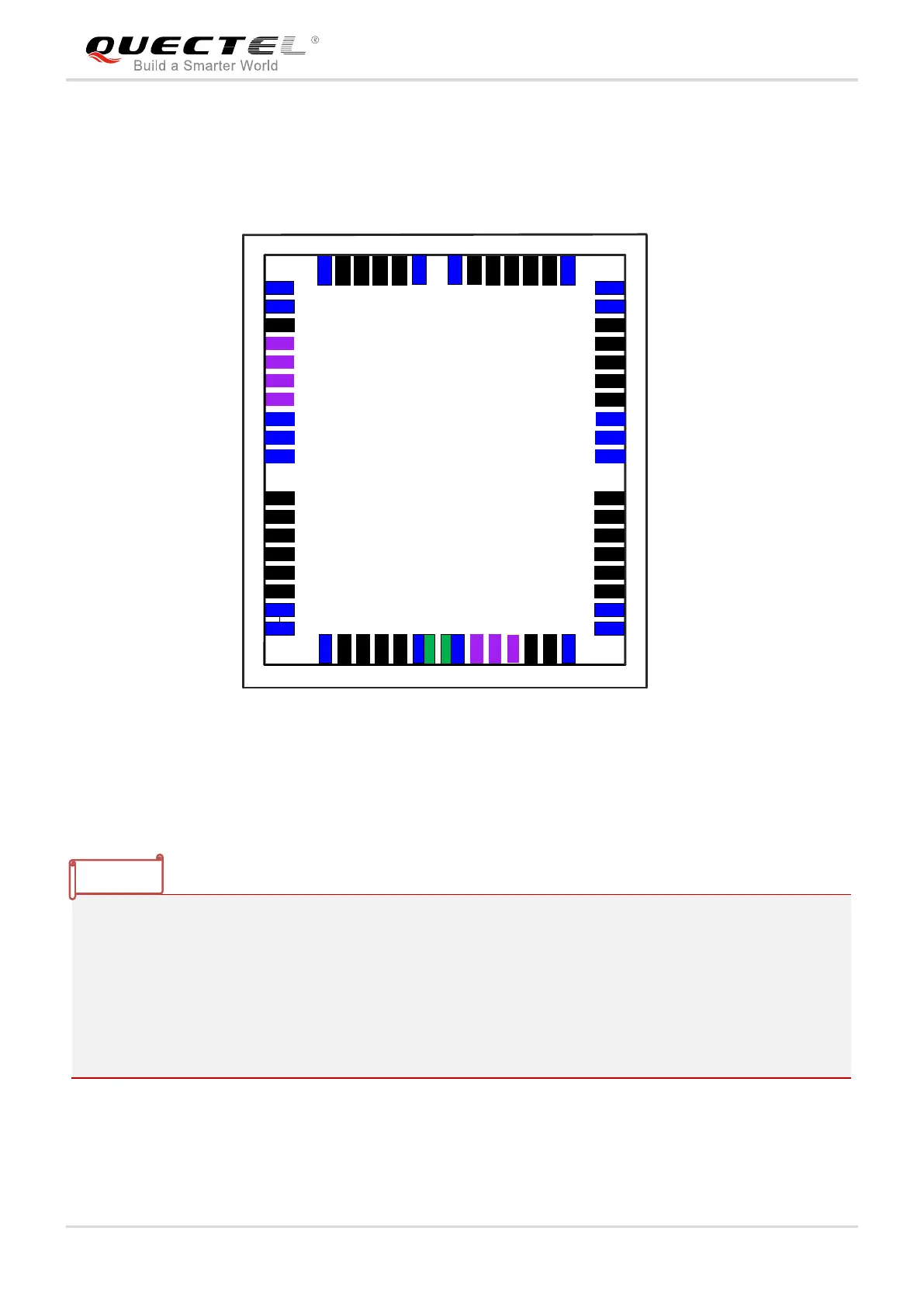
The following figure shows the combination of pin assignment for UG96, UG95 and M95 R2.0.
1. The blue pins of UG96&UG95 are the additional pins compared with M95 R2.0.
2. The pin names marked in red in the inside area are M95 R2.0’s.
3. The black pins of UG96, UG95 and M95 R2.0 are compatible pins in main functions.
4. Due to the different functions of pin 24/25 of UG96&UG95 and the green pins of M95 R2.0, different
resistors need to be mounted when using UG96, UG95 or M95 R2.0 for compatible design. For
details, please refer to document [4].
5. The purple pins are different pins in the main functions.