HSPA/UMTS/GSM/GPRS Module Series
UG96&UG95&M95 R2.0 Compatible Design
UG96&UG95&M95 R2.0_Compatible_Design 25 / 42
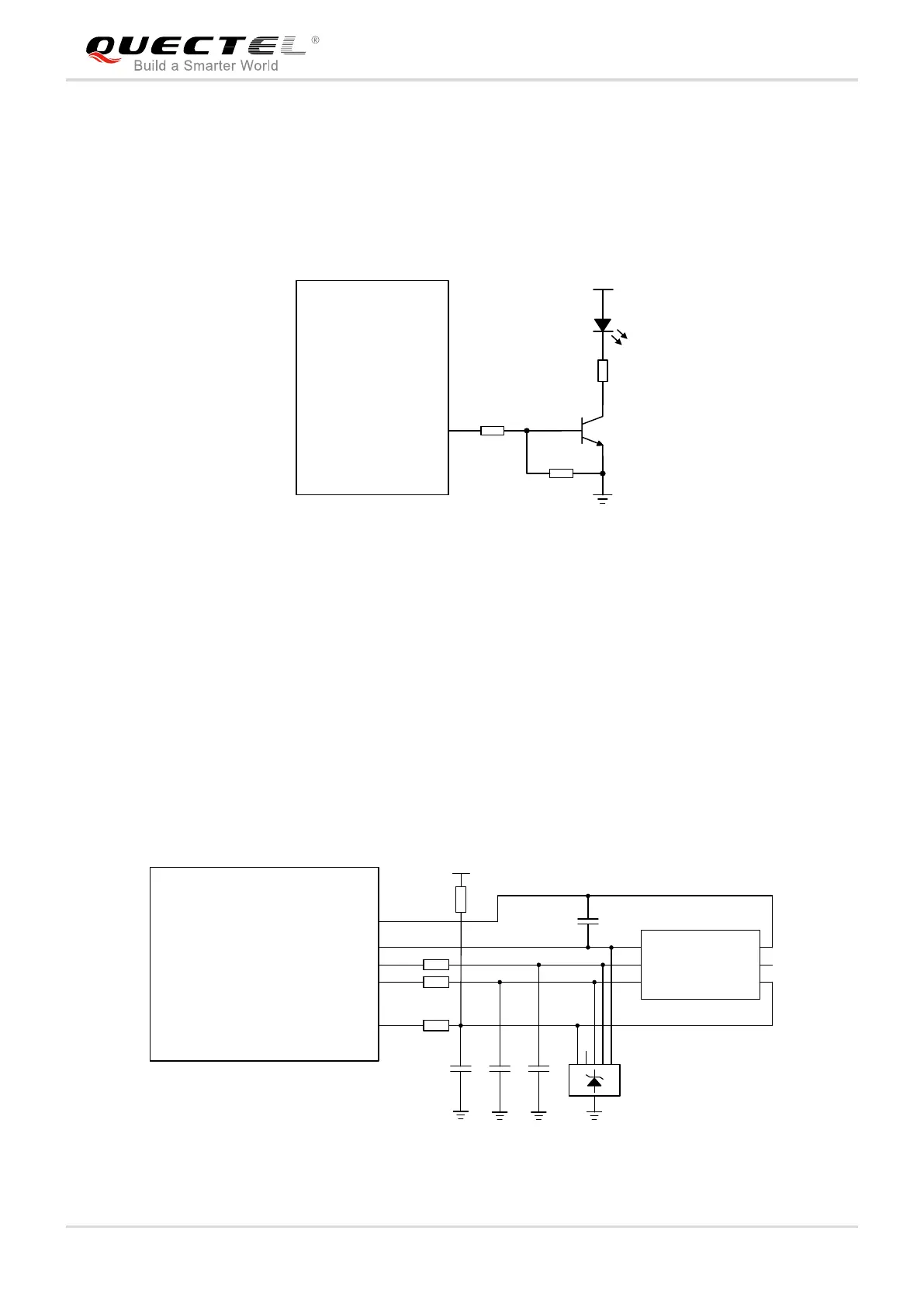
4.5. Operation Status Indication
The STATUS pin is set as the module’s operation status indicator. It will output high level when module is
powered on. The following figure shows the reference design of driving LED for STATUS.
4.7K
47K
VBAT
2.2K
STATUS
UG96/UG95/M95 R2.0
Figure 12: Reference Circuit of STATUS
4.6. (U)SIM Interface
(U)SIM interface of UG96/UG95 and M95 R2.0 supports 1.8V or 3.0V USIM/SIM cards by default. The pin
assignment of UG96/UG95’s (U)SIM interface is compatible with that of the M95 R2.0’s (U)SIM1 interface,
except that UG96/UG95’s pin SIM1_PRESENCE is not compatible with M95 R2.0’s USIM_PRESENCE.
A reference design of 6-pin (U)SIM interface is shown in the figure below:
22R
22R
22R
100nF
(U)SIM card connector
GND
ESD
33pF 33pF 33pF
VCC
RST
CLK IO
VPP
GND
GND
15K
USIM_VDD (UG96/UG95)
USIM_GND (UG96/UG95)
Module
SIM_GND (M95 R2.0)
USIM_VDD (UG96/UG95) SIM1_VDD (M95 R2.0)
USIM_RST (UG96/UG95) SIM1_RST (M95 R2.0)
USIM_CLK (UG96/UG95) SIM1_CLK (M95 R2.0)
USIM_DATA (UG96/UG95) SIM1_DATA (M95 R2.0)
SIM1_VDD (M95 R2.0)
Figure 13: Reference Design of 6-Pin (U)SIM Interface