12
EN
INSTALLATION AND USE MANUAL QUICK MC² X19 REV002A
3 - Introduction
Load generated by MC²X19
To calculate the structure sizing load use a safety factor (R = 3)
18700 N·m X 3 = 56100 N·m
(1Kg = 9,81 N·m)
3.1 - Preliminary technical checks
Before proceeding to the installation, it is essential to make sure that the position chosen and the boat structure
can withstand and enable the transfer of the loads generated by the gyroscope on the hull.
This document contains the instructions that are necessary for boat manufacturers and marine equipment installers to
assemble and commission the Quick
®
MC² gyro stabilizer.
3.0 - General information
Quick stabilizers have been designed for fixed installations in a protected space.
Taking into account the wide range of hulls and types of boats, the installer shall be responsible for building a solid
base that makes the stabilizer an integral part of the boat structure.
Nonetheless, Quick
®
is providing below some purely indicative illustrations that could be useful (See section 6.0).
The stabilizer’s installation and following inspection and repair operations must be performed exclusively by qualified
personnel.
The installer shall be responsible for the correct mechanical fixing, for the correct electrical connection, as well as for the
effective stabilizer operation after its installation on the boat.
This device must not be used by people (including children) with reduced physical, sensory or mental abilities.
QUICK
®
SpA will not accept responsibility for direct or indirect damages caused by improper use of the equipment.
BEFORE PROCEEDING TO THE STABILIZER'S INSTALLATION, ALL THE PROCEDURES
DESCRIBED AND ILLUSTRATED IN THIS INSTALLATION MANUAL MUST BE CAREFULLY
READ AND CORRECTLY UNDERSTOOD.
IF IN DOUBT, IMMEDIATELY CONTACT YOUR NEAREST AUTHORISED QUICK
®
DEALER.
If the installer do not able to guarantee that the boat structure is
able to withstand and transfer the loads in the hull generated by
the gyroscope, a qualified technician or a naval engineer should
intervene in order to carry out a suitable structural analysis on site.
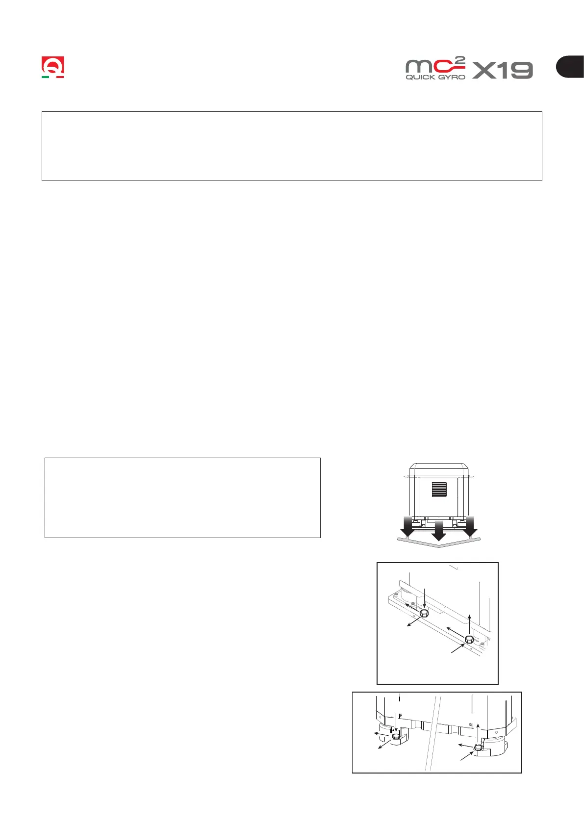
The supporting base must be properly dimensioned in order to
withstand the declared stabilizing torque (Nm).
By sharing the total stabilizing torque on the three drections for
each fixing screw (8 screws), the following torque will result on each
dimension:
• Fz: 33 kN
• Fx: 21 kN
• Fy: 3 kN
The above-mentioned efforts must be considered to work
simultaneously.
These efforts don’t include voltages introduced by marine efforts
during navigation.
with base plate (optional)
+Fz
+Fx
-Fz
-Fy
-Fx
+Fz
+Fy
-Fy
+Fx
-Fz
-Fx
+Fy