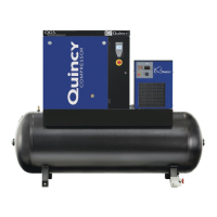
QR 310 Quincy Compressor
50214-105, March 2005 22 3501 Wismann Lane, Quincy IL - 62305-3116
HEAD ASSEMBLHEAD ASSEMBL
HEAD ASSEMBLHEAD ASSEMBL
HEAD ASSEMBL
Y 1907PY 1907P
Y 1907PY 1907P
Y 1907P
(control version P)
ItemItem
ItemItem
Item
PartPart
PartPart
Part
NumberNumber
NumberNumber
Number
Qty.Qty.
Qty.Qty.
Qty.
NumberNumber
NumberNumber
Number
DescriptionDescription
DescriptionDescription
Description
1 1 1907 head
2 2 4610X1 suction valve assembly
2.1 1 4610 valve seat
2.2 1 1549 valve bumper
2.3 1 1552-001 valve disc
2.4 1 1202 valve spring
3 4 1556 valve gasket
4 4 3008 holddown screw/ (@ 60 ft.-lbs.)
5 4 1555 cap
6 2 1553X3 discharge valve assembly
6.1 1 1553 valve seat
6.2 1 3010 valve bumper
6.3 1 1552-001 valve disc
6.4 1 1368 valve spring
7 1 2961-100 pressure relief valve
8 1 2709 elbow compression fitting, 5/16 tube x 1/8 npt, 90°
9 4 1554 gasket
4610X Replacement Suction Valve Assembly
includes suction valve assembly & gasket
1553X1 Replacement Discharge Valve Assembly
includes discharge valve assembly & gasket
Maintenance PartsMaintenance Parts
Maintenance PartsMaintenance Parts
Maintenance Parts
*
*High pressure compressors and DNV certified applications require 1907HPS head in lieu of 1907 head.
@ Indicates torque value (dry threads). Tighten multiple bolts, capscrews & hex nuts in a criss-cross or alternating pattern. Bring
each fastener to the recommended torque specification in even increments.