Section III - Installation
14 Quincy Compressor
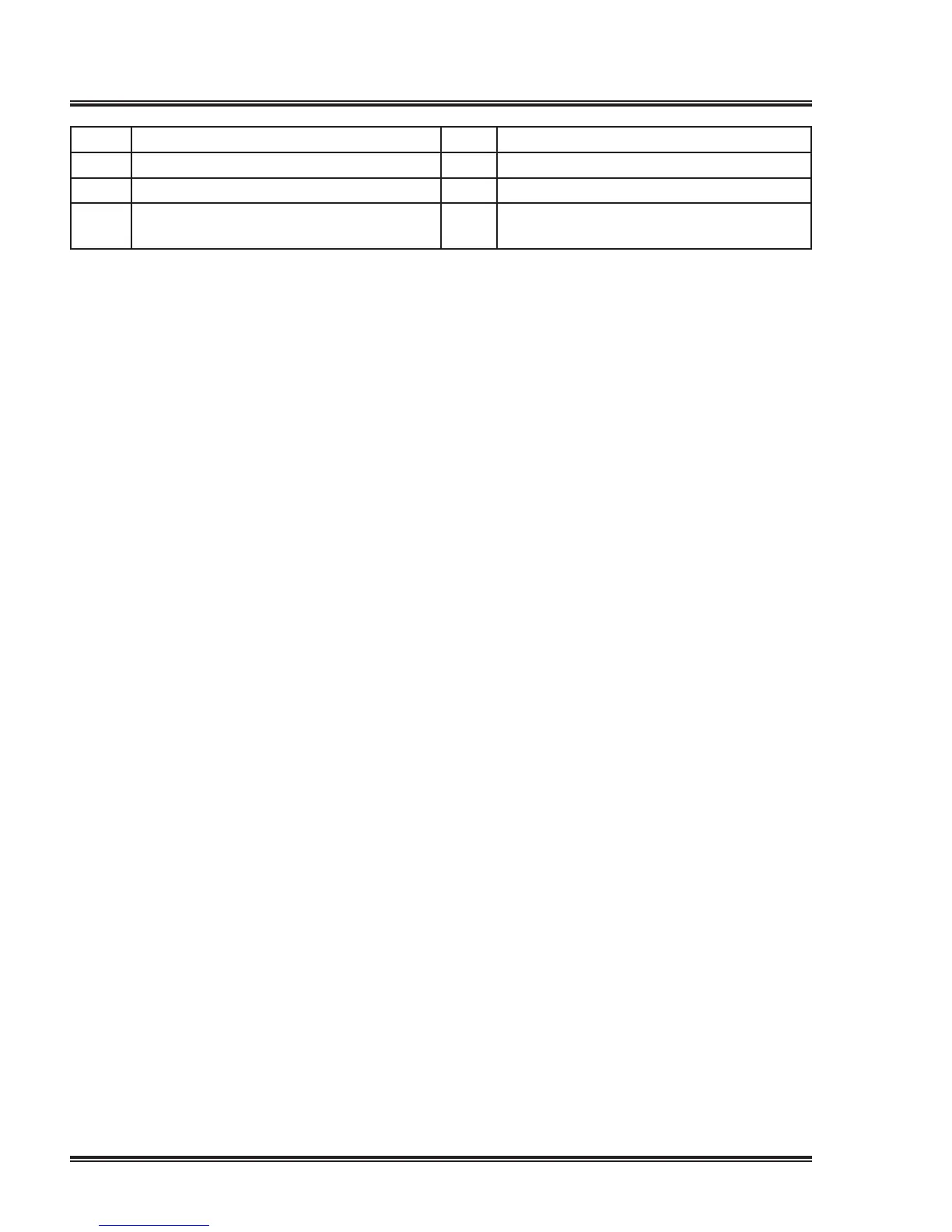
1 Dryerservicepanel 5 Condensate drain
2 Service panel 6 Manual drain
3 Supply cable 7
Automaticdrain
4 Minimum area to be reserved for ser-
vicing purposes
Recommendations
1.Installthecompressoronalevelhorizontalindustrialoor,suitablefortakingthe
weightofthecompressor.Thelocationmustbefrost-freeandpreferablylowdust
location.Thecompressorunitmustbeinstalledonaleveloor.
2.Deliverypipe.Thepressuredropinthedeliverypipecanbecalculatedfrom:
Δp=(Lx450xQ
C
1.85
) / (d
5
xP),with
d = inner diameter of the pipe in mm
Δp=pressuredropinbar(recommendedmaximum:0.1bar(1.5psi))
L = length of the pipe in m
P=absolutepressureatthecompressoroutletinbar
Qc = free air delivery of the compressor in l/s
3.Ventilation:theinletgridsandventilationfanshouldbeinstalledinsuchawaythat
anyrecirculationofcoolingairtothecompressorisavoided.Themaximumair
velocitythroughthegridsis5m/s(16.5ft/s).Themaximumallowablepressure
dropoverthecoolingairductsis30Pa(0.12inwc).Themaximumairtemperature
atthecompressorintakeopeningis40˚C(104˚F).
Take care that the temperature of the ambient air and the cooling air may never be
lower than 0 °C (32 °F) to avoid freezing of condensate.
Therequiredventilationcapacitytolimitthecompressorroomtemperaturecanbe
calculatedfrom:
•Q
V
=1.06N/Δt for compressors without integrated dryer.
•Q
V
=(1.06N+0.2)/Δt for compressors with integrated dryer.
with
Q
V
=requiredventilationcapacityinm
3
/s
N=shaftinputofthecompressorinkW
Δt = temperature increase in the compressor room in °C
4.Airreceiver:anoptionalairreceivercanbenecessarytolimitthecyclefrequency.
Recommendedmaximumis20startsperhour.
5.Optional filters can be installed in the pressure line downstream the air outlet valve,
e.g.:
•ADD
+
filterforgeneralpurposefiltration.Thefiltertrapssolidparticlesdownto1
micron.
•APD
+
filterforfiltrationdownto0.01micron.APDfiltermustalwaysbeinstalled
downstreamaDDlter.
6.Controlcubiclewithmonitoringpanel.
7.Compressoranddryercoolingairoutlet
 Loading...