Quincy Compressor5
• Introduction
• Flow diagram
• Refrigerant dryer
Introduction
General
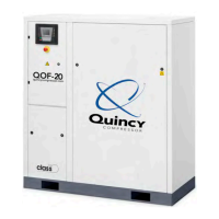
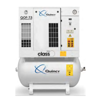
QOF-2,QOF-3,QOF-5,QOF-7.5arestationary,singlestage,oil-freecompressors,drivenby
an electric motor.
Thecompressorsarecontrolledbyapressureswitch.
Thecompressorsareenclosedinasounddampeningenclosureandareaircooled.
Availableversions:
•Thebasicversion(QOF)comprisesthemotor,thecompressorelement,anaircooled
aftercooler and the regulation and protection components.
•TheQOFwithdryerisaQOF,completedwithanintegratedrefrigerantdryer.
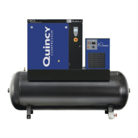
Thebasicversion(referredtoastheoormountedversion(FM))doesnotincludeanair
receiver.Anairreceiverisavailableasoption.
Availableoptions:
•Airreceiverof30l(7.93USgal),270l(71.3USgal)or500l(132USgal).The30l
receiverconsistsofamodulewiththree10l(2.64USgal)receivers.The30lreceiver
option includes an electronic drain.
•Receivermountedversion(270land500l):electronicdrainontheairreceiver
•Floormountedcompressorswithoutrefrigerantdryer:waterseparatorontheoutlet
•Prefiltermatsontheairinlet
•Phasesequencerelay(on3-phaseunits)
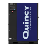
QOF
Thecontrolpanelcomprisesapressuregauge,anhourmeterandastartbutton.Thecompressor
iscontrolledbyapressureswitch(PS).
Theelectriccomponentsarelocatedinthecubiclebehindthefrontpaneldoor.
Acheckvalve(CV)preventslossofcompressedairwhenthecompressorisstopped.A
temperatureswitchandasafetyvalve(SV)protectthecompressorelementagainstoverheating
andtoohighpressurerespectively.Thecompressedairiscooledbyanaircooler(Ca).
Singlephaseunitsareequippedwithaventvalveforeasystarting.
 Loading...