36
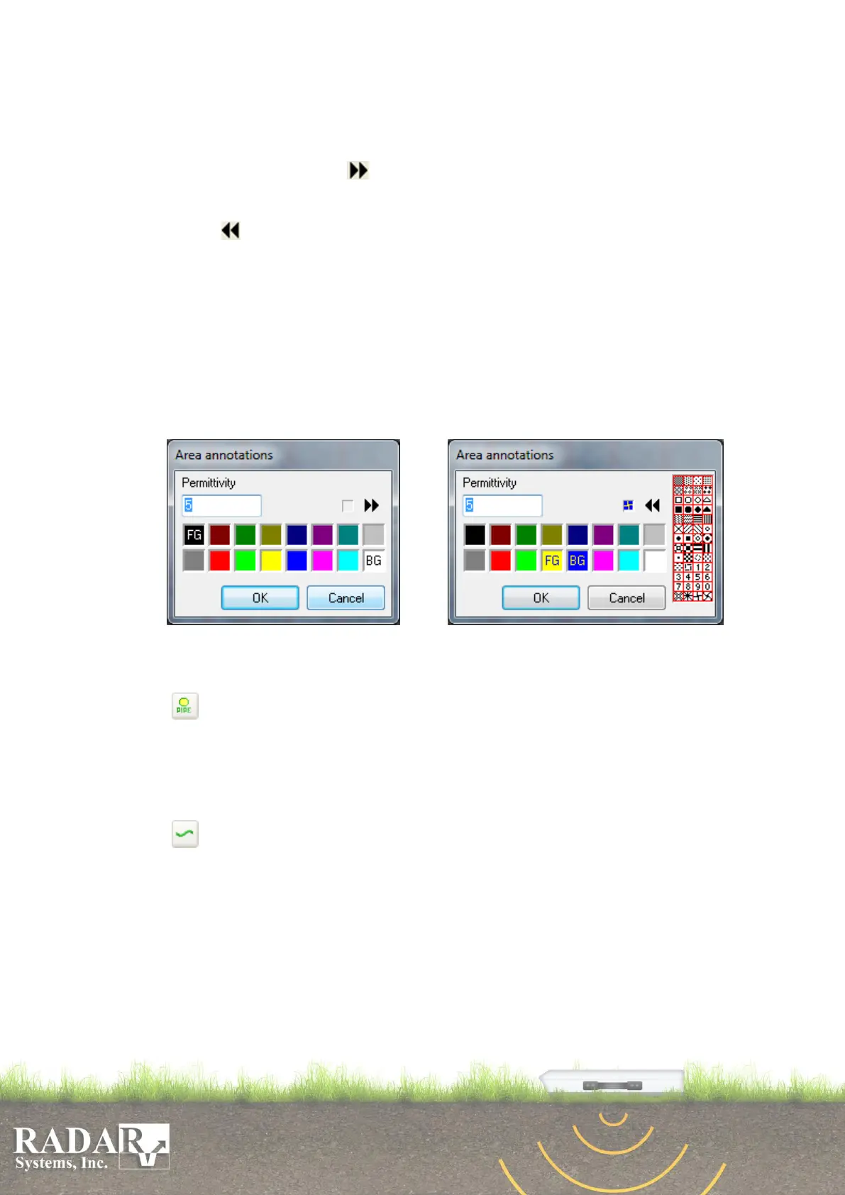
color (FG) in the appearing dialogue box (Fig. 10.7.a) by clicking left mouse button
on any of 16 colors listed, and enter the mean velocity for the area before selection
of an area in the profile. Also you may select one of 52 available patterns (8x8
pixels each) for are painting in case if you need to fill selected area with a pattern.
To do it press the button and select the pattern in the appearing right part (Fig.
10.7.b). Pattern colors shall be a function of the basic foreground color (FG) and
selected background color (BG). If you don't need to use a pattern, simply press the
button . Press OK button to continue. You have to click by left mouse button
each vertex point of expected area on the, when you are done, press right mouse
button and the last point will connect with the first one, completing the area and
painting it with the pattern or the just a color you have chosen. There is no need to
click all boundary points, while adjacent areas drawing. It is enough to set only
three points on an existing boundary zigzag line, what contacts with the new
expecting area (the fist point of boundary line, an any point in between and the last
point of the boundary). Boundary zigzag line will be automatically constructed
repeating the marked outline portion of an existing area after you place the third
point, now you can finish drawing adjacent area with any additional points.
Fig. 10.7.a. Dialogue Box for Area Fig. 10.7.b. Dialogue Box for Area Tuning with
Tuning. Pattern Selection.
o Pipe - is used for symbolic display of the cross-section of a pipe or a cable on
the profile. After selecting this option press and hold left mouse button and then
move the mouse as if you are selecting the area when you are done release mouse
button, you will be asked to specify Pipe fill color, to confirm press OK button. To
remove the pipe place the cursor on it, click the right mouse button and select
option Delete.
o Picket – used to automatically select interfaces between media along the
profile from the maxima of the reflected signals with an option to save the defined
interface as an ASCII file. After selecting this option dialog window will appear
letting you to select color and width of line depicting the interface. Confirm your
choice by pressing the OK button, then place the pointer to the corresponding
signal line of a ground interface and press the left mouse button. In appeared dialog
box specify a profile section, within which interface selection will be made. Press
OK button again and the line of your chosen color and width will be displayed
coinciding with the signal line. If appeared line does not coincide with the signal
correctly please use Edit picket option.