54
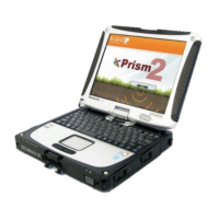
Fig. 14.2. Type profile shot using Common Depth Point technique.
Three signals are clearly visible on the provided profile, namely:
1 – Air wave path signal. Always appears as an inclined straight line.
2 – Signal path reflected from the first layer interface.
3 – Signal path refracted at the first layer interface and reflected from the
second layer interface.
Important! After you finished sounding and saved the file, be sure to enter the initial
and final antenna spacing in Output parameters.
To calculate medium characteristics (wave velocity or permittivity) by hodographs of
the received signals, activate Hodograph button in the Main menu or use Tools/Mouse
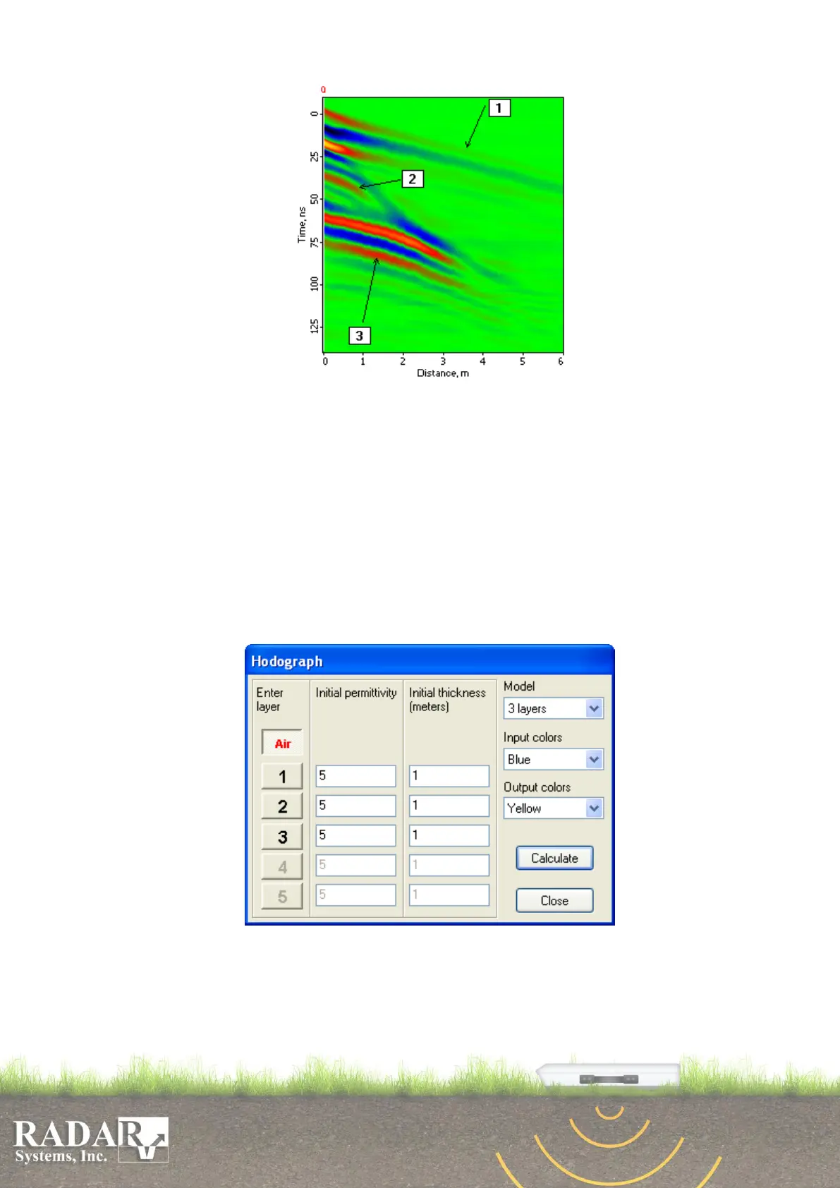
actions/Hodograph menu option. It will open the Hodograph dialog box.
Fig. 14.2. Hodograph Taking dialog box
1. Using Model option in the dialog box, select the quantity of calculation model
layers. This quantity depends on how many layer interfaces are visible in your
profile; it may range from 1 to 5.