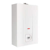
What causes general PCB malfunction in Radiant Boiler?
- LLauren ParkerSep 12, 2025
General PCB malfunction in a Radiant Boiler is caused by a microprocessor malfunction where it detects a wrong signal. The PCB resets the error automatically.

What causes general PCB malfunction in Radiant Boiler?
General PCB malfunction in a Radiant Boiler is caused by a microprocessor malfunction where it detects a wrong signal. The PCB resets the error automatically.
What happens if the electric power supply is outside the operation range for a Radiant Boiler?
If the electric power supply to your Radiant Boiler is outside the operation range (?160 / ?285 volts), check the power supply network. The error disappears automatically when the power supply is back within the required range.
Crucial safety guidelines and precautions for the installation, operation, and maintenance of the appliance.
Declaration of compliance with standards and information on materials used in the appliance.
Detailed specifications including heat input, output, efficiency, and gas/water/electrical ratings.
Physical measurements of the boiler and its connection ports for water, gas, and flue systems.
Identification and description of the main internal parts of the boiler unit.
Graphical representation of pump head and flow rate at different speeds.
Schematic illustration of the water flow through the boiler's internal components.
Technical characteristics and functions of the boiler's printed circuit board.
Description of the buttons, display, and terminals on the boiler's control panel.
Explanation of how to access and interpret information displayed in the INFO menu.
Guidelines on legal standards and specific requirements for boiler installation.
Recommendations for ventilation and placement of the boiler within the installation room.
Procedures for safely unpacking the boiler and handling packing materials.
Instructions for physically installing the boiler onto a wall and marking connection points.
Details on connecting the heating circuit and D.H.W. supply and return pipes.
Instructions for connecting the D.H.W. circulating pipe to the boiler.
Guidelines for safely connecting the boiler to the gas supply line.
Important warnings and procedures for making safe electrical connections to the boiler.
Requirements for connecting the flue system to ensure correct and efficient operation.
Specifications for the horizontal concentric flue kit Ø60/100 mm, including length limits.
Specifications for the horizontal twin pipe flue kit Ø80/80, including length limits and bend effects.
Specifications for the vertical concentric flue kit Ø80/125, including length limits.
Instructions for installing and setting adjustable diaphragms for coaxial flue systems.
Instructions for installing adjustable diaphragms on the air intake for twin pipe flue systems.
Tables showing diaphragm regulation based on flue length for kits A, B, and C2.
Critical warnings for qualified personnel performing initial boiler setup and checks.
Step-by-step guide for filling the heating system and checking pressure.
Explanation of the boiler's automatic frost protection mechanisms and recommendations.
Detailed steps for starting the boiler for the first time, including gas checks and mode selection.
List of adjustable parameters, their values, and corresponding functions for boiler regulation.
Instructions on how to navigate and enter the boiler's parameter adjustment menu.
Guide to modifying parameters like boiler type, gas supply, and heating temperature settings.
Procedure for adjusting gas valve settings for maximum output and pressure.
Tables detailing gas pressure and consumption specifications for different gas types.
Graphical representation of boiler output capacity relative to gas pressure.
Steps for converting the boiler to operate with different gas types like LPG or Natural Gas.
Essential safety precautions before commencing any maintenance operations on the boiler.
Recommended checks for ensuring safe and efficient boiler operation during annual servicing.
Instructions for safely removing panels to access internal components for maintenance.
Procedure for safely draining the central heating system for maintenance or seasonal storage.
Schematic diagrams illustrating the electrical connections of the boiler's components.
Instructions for connecting optional outdoor sensors and remote control units.
Guide to identifying and resolving common boiler error codes and their causes.
Explanation of specific function codes (F07, F08, F09, F28) used for testing and operation.
List of main components with their corresponding part codes for ordering replacements.
 Loading...