EasyManuals Logo

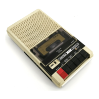
Radio Shack CCR-81 Reference Handbook

Radio Shack CCR-81
116 pages
To Next Page IconTo Next Page
To Previous Page IconTo Previous Page
Page #112 background imageLoading...
Page #112 background image
MREQ
240
19
2MREQ
*"
®
(TO
Z23,
pins 4 and
12)
SEE
,HEET
2
KEf
IOARD
ROM
@
--
--
ROM
'"
08~
M
07
'T6'
"
AI3
3
J
TO
AI4
4
238
AI5
5
(pi
n$
10,12,61
GND
29
MREQ
R9
®
~~___
D
r
---------~~,
I I
I I
R8 I
QS
lOOK
I
MPSS3906
I
I
cia
+
CI4
CRI I
:
I~t:~
O'~~eF¢
:~~/:3S
:
I I
;;sv
I~
0'11~0~
I
)0
I
29
(32
PLACES)
I
;
PL
AC
E::A
37
C2 2,C2
3,
C29,
I
16-C19
C31,C33,C3S-C38,
I
'39
C40,C41,
C44-C56
I
L
~
(Revision D and after)
ROM
'"
-
.,
74LS011l
R62
47K
L--.JVV'v-_-+_---()-+
5v
Is
14
13
qRJ
Z3
I
4--·
I
1.'74
b..;:6
........
--'M"'E:.:.Mc.....:;'le.-
)-'8~---'S::..j
- f I
74LSe0
:
~
I
I
I
I
I
__
J I
L
~_--------J
RD'"
13
RAM·
A. Pins 5 and 4
of
Z74
connect
directly
to
signal
~MREQ*.
B.
Pins
20
of Z33
and
Z34
are
tied together.
C.
DIP
shunt
Z3,
pins
6,7
and
8 are tied
together
and go
to
pins
20
of
Z33
and Z34.
The signal
is
now called ROM*.
D.
Pin
39
is
now
ground.
+5 volts still goes
to
0.1
MF
capacitors (32).
Figure 28. Changes to the TRS-80 Schematic Diagram (Figure 29)
(Revisions D and E)
III

Other manuals for Radio Shack CCR-81

Questions and Answers:

Question and Answer IconNeed help?

Do you have a question about the Radio Shack CCR-81 and is the answer not in the manual?

Radio Shack CCR-81 Specifications

General IconGeneral
BrandRadio Shack
ModelCCR-81
CategoryDesktop
LanguageEnglish

Related product manuals