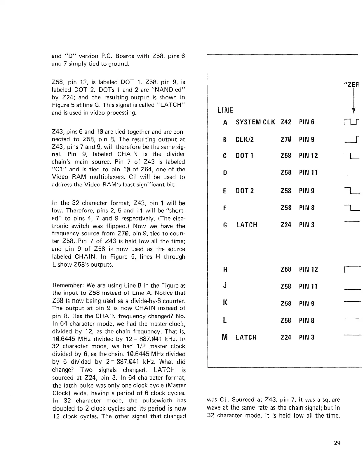
LINE
A
SYSTEM
ClK
Z42
PIN
6
B
ClK/2
Z70
PIN
9
C
DOT1
Z58
PIN
12
D
Z58
PIN
11
E
DOT
2
l58
PIN
9
F
Z58 PIN 8
G
lATCH
Z24
PIN
3
was
Cl.
Sourced at
Z43,
pin
7,
it
was
a square
wave at the
same
rate
as
the chain signal;
but
in
32 character mode,
it
is
held
low
all the time.
and
"D"
version
P.C.
Boards
with
Z58, pins 6
and 7 simply tied
to
ground.
Z58. pin 12,
is
labeled DOT
1.
Z58, pin 9,
is
labeled DOT
2.
DOTs 1
and
2
are
"NAND-ed"
by Z24;
and
the resulting
output
is
shown in
Figure 5 at line
G.
This signal
is
called
"LATCH"
and
is
used
in video processing.
Z43, pins 6
and
10
are
tied together
and
are
con-
nected
to
Z58, pin
8.
The
rE?sulting
output
at
Z43, pins 7 and
9.
will
therefore
be
the
same
sig-
nal.
Pin
9, labeled
CHAIN
is
the divider
chain's main source.
Pin
7
of
Z43
is
labeled
"Cl"
and
is
tied
to
pin 10
of
Z64. one
of
the
Video RAM multiplexers.
Cl
will
be
used
to
address the Video RAM's least significant bit.
In the
32
character format, Z43, pin 1
will
be
low. Therefore, pins
2,
5 and
11
will
be
"short-
ed"
to
pins 4, 7
and
9 respectively. (The
elec-
tronic
switch
was
flipped.)
Now
we
have
the
frequency source from
Z70, pin 9. tied
to
coun-
ter
Z58
..
Pin
7
of
Z43
is
held
low
all the time;
and pin 9
of
Z58
is
now
used
as
the source
labeled
CHAIN.
In Figure
5,
lines H through
L show Z58's outputs.
Remember:
We
are
using Line B in the Figure
as
the
input
to
Z58
instead
of
Line A. Notice that
Z58
is
now
being
used
as
a divide-by-6 counter.
The
output
at pin 9
is
now
CHAIN
instead
of
pin
8.
Has
the CHAIN frequency changed? No.
In
64
character mode,
we
had the master clock,
divided by 12,
as
the chain frequency. That
is,
10.6445 MHz divided by
12=887.041
kHz. In
32
character mode,
we
had
1/2 master clock
divided
by
6,
as
the chain. 10.6445 MHz divided
by
6 divided
by
2 = 887.041 kHz. What did
change?
Two
signals changed. LATCH
is
sourced at Z24, pin
3.
In
64
character format,
the latch pulse
was
only
one clock cycle (Master
Clock) wide, having a period
of
6 clock cycles.
In 32 character mode, the pu Isewidth
has
doubled
to
2 clock cycles
and
its period
is
now
12
Clock cycles. The other signal
that
changed
H
J
K
l
M lATCH
Z58
PIN
12
Z58
PIN
11
Z58 PIN 9
l58
PIN
8
Z24
PIN 3
"lEA
1
ru
29

 Loading...


