_---~10
Va
______
..J
---------,
I
I
I
OPAMP
POWER
Vc
-----------
11
7.15
VOLT
t----~
OP
AMP
POWER
V+
Za
I
1
L
__
V-
Vref
+
COMP
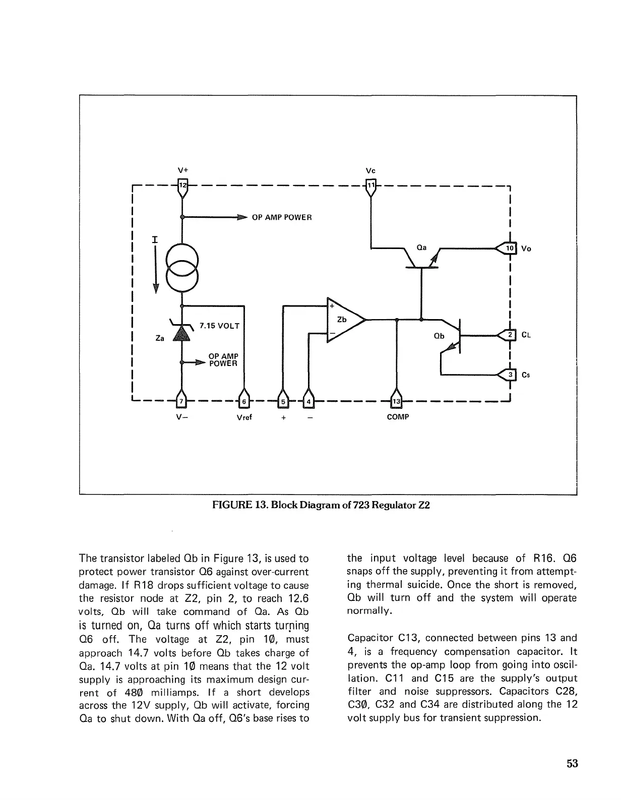
FIGURE 13. Block
Diagram
of723 RegulatorZ2
The
transistor labeled Ob
in
Figure 13,
is
used
to
protect
power
transistor
06
against over-current
damage. If R
18
drops
sufficient voltage
to
cause
the
resistor node
at
Z2, pin 2,
to
reach 12.6
volts, Ob will
take
command
of
Oa. As Ob
is
turned
on,
Qa
turns
off
which
starts
turfling
06
off.
The
voltage
at
Z2, pin 10,
must
approach
14.7 volts before Ob takes charge
of
Oa. 14.7 volts
at
pin
10
means
that
the
12
volt
supply
is
approaching its maximum design cur-
rent
of
480
milliamps. If a
short
develops
across
the
12V supply, Ob will activate, forcing
Oa
to
shut
down. With Oa off,
06's
base rises
to
the
input
voltage level because
of
R16.
06
snaps
off
the
supply, preventing
it
from
attempt-
ing thermal suicide. Once
the
short
is
removed,
Ob will
turn
off
and
the
system will
operate
normally.
Capacitor C13,
connected
between pins 13 and
4,
is
a frequency
compensation
capacitor. It
prevents
the
op-amp loop from going
into
oscil-
lation. C11 and C15 are
the
supply's
output
filter and noise suppressors. Capacitors C28,
C30, C32 and C34 are distributed along
the
12
volt
supply bus for
transient
suppression.
53

 Loading...


