SCHEMATICS
BASIC I
ROMS
Since the TRS-80 went into production,
there were
three
major
PCB
changes.
These
changes reflect
different
vendor's
responses
to
system requirements
as it pertains
to the ROM
(Read Only Memory). In
the manufacturing
process, certain
vendors
were
able
to supply ROMs to
the factory
at differ-
ent
times.
Hence
there are three
major types of ROMs.
There were slight
PCB
Modifications
as each
ROM
was
used.
INTEL
EPROMS
The first mass-produced ROM
type
was the Intel 2616
EPROM
(Erasable, Programmable,
Read
Only Memory).
An Intel ROM
may be identified by
part number,
the
Intel
trademark
and the white painted crystal
window. There
are
two Board
levels that use the Intel ROM.
The
first Board level may be
identified by the
"A" right
after the part number on the
etched side. For
example,
a
Board
marked "TRS-80
1700069A" is
an
"A"
level Board.
It
may also be identified by
major wire modifications
in
two areas. With the
PCB
upside
down and
the
DIN
plugs
facing
away from you, an "A" Board
has several
wires on
the right
side
between
you and the DIN plugs.
It also has
wiring
to the left of the ROMs, closest
to the
CPU
(Central
Processing Unit, the Z-80). The
wire mods
on the right side
are connections
in the video, horizontal,
and vertical sync
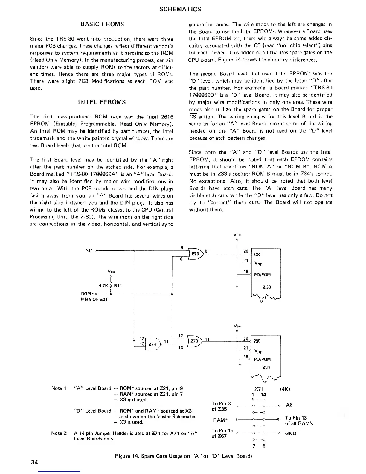
generation
areas. The wire
mods
to
the left are
changes in
the Board to
use the Intel
EPROMs. Whenever a Board uses
the
Intel
EPROM
set, there
will
always
be some added
cir-
cuitry associated
with the CS (read "not
chip select") pins
for each device. This added
circuitry uses spare gates on
the
CPU
Board.
Figure 14
shows the
circuitry
differences.
The second Board
level that used
Intel
EPROMs
was the
"D"
level, which may
be identified by the
letter "D" after
the part
number. For
example,
a Board
marked
"TRS-80
1700069D" is
a
"D" level
Board. It may also be identified
by major wire modifications
in only one area. These wire
mods
also utilize the spare gates on the
Board for proper
CS action.
The wiring
changes for this level Board is the
same
as
for an "A" level Board except
some of the wiring
needed on the
"A" Board is not
used
on
the "D" level
because
of etch pattern changes.
Since both
the "A" and
"D" level Boards
use the Intel
EPROM,
it
should
be
noted that each
EPROM
contains
lettering that identifies
"ROM A"
or
"ROM B".
ROM
A
must be in Z33's socket;
ROM B must be in
Z34's
socket.
No exceptions!
Also,
it
should be noted that
both level
Boards have
etch cuts. The "A" level
Board
has
many
visible
etch
cuts while the
"D" level has only a few. Do not
try
to
"correct" these
cuts. The Board will not operate
without
them.
A11
>-
Vcc
4.7K 5
R11
ROM*
t>
PIN9
0FZ21
10
Note 1
:
"A" Level
Board
"D" Level Board
-
ROM*
sourced
at
Z21,
pin 9
-
RAM*
sourced
at
Z21,
pin 7
-
X3
not
used.
-
ROM* and RAM* sourced
at X3
as
shown
on the
Master
Schematic.
-
X3
is
used.
Note
2:
A 14 pin Jumper Header is used
at
271 for
X71 on "A'
Level Boards only.
Vcc
20
<
CS
21
<
v,
18
PP
PD/PGM
Vcc
20
21
18
Z33
CS
V
PP
PD/PGM
Z34
X71
1
14
o-
-o
To
Pin
3
of 235
RAM*
To
Pin
15
of
267
(4K)
A6
o—
~o
-o
o-
c—
-o
-o
o-
To Pin
13
of all RAM's
GND
o-
-o
7
8
34
Figure
14. Spare
Gate Usage
on
"A" or "D" Level Boards

 Loading...


