RC1180-MPC1/RC1701HP-MPC1 User Manual (rev. 1.1)
RC1180-MPC1
USER MANUAL RC1701HP-MPC1
2 Wireless M-Bus Embedded Protocol
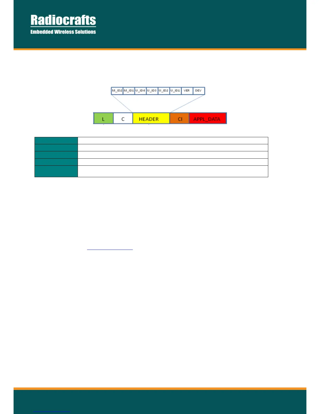
During the RF transmission, the module transmits a data frame according to EN13757-3/4. At the MBUS receiver,
the format of the payload will look like this:
Figure 1 – Wireless M-Bus Packet
Added automatically. Does not include itself, nor START/STOP bytes.
Configured in module. Added automatically.
Configured in module. Added automatically.
Configured in module. Added automatically.
Application data including packet counter, tamper info and pulse counting values for
the two inputs (4 bytes for each pulse input). Added automatically.
The MPC1 module will transmit the data points using the M-Bus application protocol (EN 13757-3). The type and
number of data points included in the message depends on the configuration of the module (one or two pulse
inputs). The DIF and the VIF are the descriptors used.
A “short header” (transport layer) is used for status and encryption information. The STATUS byte contains the
battery alarm bit (0x04) and tamper bit (0x20). The tamper monitoring is enabled through the module configuration.
To fully understand the protocol and details like packet format, configuration, sleep modes and so on for a
complete Wireless M-Bus setup, please refer to the Data Sheet and the User Manual for RC1xx0-MBUSx found on
the Radiocrafts website www.radiocrafts.com.
 Loading...