4 Set up and use the pulse inputs
The meter pulse inputs (PULSE1/PULSE2) of the module is between GND and Pin 27/28. These are the same
input as Push Button S5/6 on the Development Board for the module. MPC_IO can enable one or two pulse inputs.
The pulse is counted on negative or positive edge. This is configurable by the configuration parameter
MPC_POLARITY.
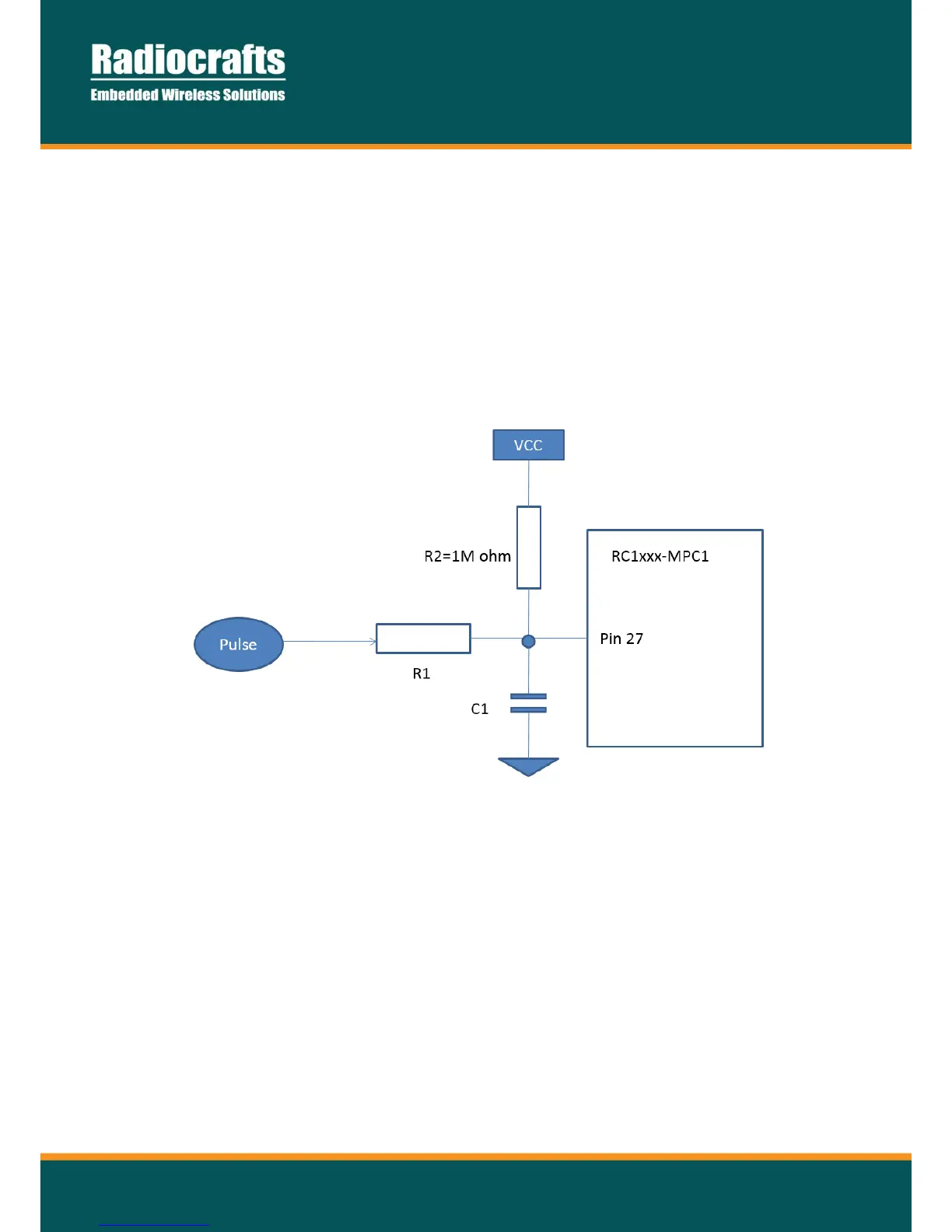
The input has configurable pull-up internally to avoid leakage current during pulse (input = 0V). This means the
external circuitry must keep the pin high to ensure no leakage. In case the pulse is generated by an open / short to
ground circuitry, a pullup to VCC is needed. You can choose between adding an external 1MOhm (mega-ohm)
resistor or enabling an internal pullup set by configuration parameter MPC_PULLUP. Adding the external pullup will
give a lower current consumption.
Figure 2 – Pulse Pin connection
C1 together with R1 can be used to filter the pulse input, but do not use too much filtering as this will reduce the
rise/fall time of the pulse.
If the UART is not connected to any circuitry during operation, make sure to include a pull-up resistor to RXD. Data
to this pin will wake up the module from sleep.
 Loading...