Do you have a question about the Radiodetection 1205CXA and is the answer not in the manual?
Explains symbols like Caution and Warning, and general safety precautions.
Introduces the Model 1205CXA as a multipurpose metallic time domain reflectometer.
Lists key features of the Model 1205CXA, such as fault location and rugged packaging.
Explains how a Time Domain Reflectometer (TDR) works using radar principles and signal reflections.
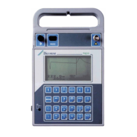
Details the components and layout of the instrument's front panel.
Explains the functions of keypad controls and how to use cursors for measurement.
Describes LCD information areas, pop-up menus, and control icons.
Explains distance calculation between cursors, battery status, and distance markers.
Lists functions available in the pop-up menu like Store, Recall, Pulse, Cable, VOP, Filter, Setup, and Print.
Outlines procedures for proper operation and achieving precise distance readings.
Explains the RANGE-PLUS operation, switching ranges, and cursor behavior.
Details how to use dual independent cursors for measuring distance on the waveform.
Explains different display modes for live and recalled waveforms.
Describes the IFD mode for detecting and displaying intermittent faults.
Explains Zoom, Vertical Gain, and Cable Type selection for waveform analysis.
Details setup options and the SUPER-STORE capability for storing and recalling waveforms.
Discusses noise filters and testing cables with power present, including safety warnings.
Explains battery charging procedures and the RS-232 interface for printing and software.
Guides users on initial setup and selecting default settings for the instrument.
Emphasizes quality connection and performing a quick cable check for TDR testing.
Explains cable impedance, VOP determination, and their importance in TDR measurements.
Provides techniques to reduce VOP error and explains how pulse width affects testing.
Discusses cable loss, attenuation, and automatic dBRL calculation for fault severity.
Describes modifying a tap plate for easier TDR testing of installed taps.
Covers missing signals, locating corroded splices, and identifying cables.
Explains using the IFD function to detect and capture intermittent cable faults.
Discusses using TDR for cable inventory, measuring, and documenting work with SUPER-STORE.
Details using TDR to detect unauthorized connections and document theft of service.
Explains that waveforms vary due to applications, cable types, and settings.
Shows example waveforms for open and short faults.
Illustrates waveforms for partial faults, splices, and attenuations from components.
Covers waveforms for splitters, water-soaked cables, and antennas.
Shows waveforms for CATV hardlines and mechanical connectors.
Details cleaning procedures and periodic inspection of the instrument and accessories.
States that the instrument has no user-serviceable parts and guides on proper disposal.
Lists physical dimensions, environmental conditions, accuracy, and range.
Details display type, power source, operating time, and output signal.
Covers resolution, noise filters, input protection, VOP formats, and accessories.
Explains how the Model 1205CXA interfaces with specific printers.
Provides a table of Velocity of Propagation (VOP) values for various cable types.
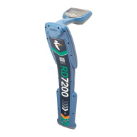
| Category | Cable and Pipe Locator |
|---|---|
| IP Rating | IP54 |
| Frequencies | 512Hz, 8kHz, 33kHz, 65kHz, 83kHz |
| Current Measurement Accuracy | ±5% (typical) |
| Operating Temperature | -20°C to +50°C |

