Do you have a question about the Radiodetection T631 TDR and is the answer not in the manual?
Product tested and supplied according to specifications, safe when used as prescribed.
Warnings regarding live cables, battery types, charging temperature, and AC adaptor use.
Details about rechargeable NiCad cells, charging duration, and initial charge cycles.
Illustrates reflected pulses for open circuit/high impedance and short circuit/low impedance faults.
Describes the unit's power options: internal batteries or external DC source.
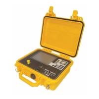
Highlights key functionalities and shows an image of the T631 front panel.
Detailed explanation of the unit's buttons and controls for operation and settings.
Describes the BNC input/output, 9-way D connector, and DC power jack.
Indicates when the internal battery is being charged.
Information on recharging, maximizing battery life, and cell replacement.
Details on using an external 12-20 V DC power source and its connection.
Information on the lithium manganese cell for memory backup and its replacement.
Precautions for operating the unit, including cable status and RF signals.
Procedure for powering on the unit and adjusting the display contrast.
Guide to re-programming distance units, dielectric parameters, impedance, and pulse selection.
Instructions for setting the velocity factor for the cable dielectric.
Method to determine PVF using dielectric constant if unknown.
Procedure to determine PVF by measuring a known length of the same cable type.
Steps for connecting the cable to the TDR unit and initial considerations.
How to set parameters and adjust gain to observe and locate cable faults.
Instructions for using the left hand cursor to eliminate test lead length or measure between features.
Method to remove the test lead length from distance measurements using the LH cursor.
How to use cursors to measure the distance between two points on the trace.
How to reset the left hand cursor to zero for normal measurements.
Using the auto "Find Fault" function to locate significant cable features.
Explains how to measure and interpret Return Loss for impedance mismatches.
Procedure to determine pulse attenuation for accurate true return loss calculation.
How to use the low-pass filter to reduce noise, especially on high gain settings.
Steps to save a live trace and associated machine settings into memory.
Procedure to retrieve and display a trace previously stored in memory.
How to display live and stored traces simultaneously for comparison.
How to display the difference between a live trace and a stored trace.
Accessing the help menu within memory mode, noting disabled parameter keys.
Instructions for connecting a printer and transferring data from the unit.
Details on setting the DIP switches on a specific printer model for interface.
Information on using PC software for data transfer and database management.
Details on gain settings and corresponding signal levels for full scale deflection.
Table showing default and available pulse widths for different ranges in auto mode.
States the company's BS EN ISO 9001 registration.
Details on internal batteries, external DC source, and AC adaptor power options.
Recommendation for returning the instrument for service and calibration every two years.
Information on potential hazards from components like NiCad batteries and electrolytic capacitors.
Guidelines for safely transporting and handling the instrument, including packaging.
Recommendations for storing the instrument in a dry environment and battery charging intervals.
Precautions for disposing of the equipment and packaging materials according to local legislation.
Information on safe operation by trained personnel and working environment considerations.
| Model | T631 |
|---|---|
| Accuracy | ±1% |
| Resolution | 0.1 m |
| Display | LCD |
| Operating Temperature | -10°C to +50°C |
| Storage Temperature | -20°C to +60°C |





 Loading...