→ The drain valve on the lower supply manifold must be pointing downwards to allow complete
drainage of the vessel.
→ The vent valve on the upper return manifold must be pointing upwards to avoid leakage of
thermofluid during drainage of the vessel.
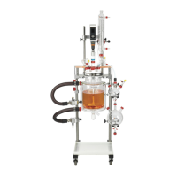
Slide a safety stop collar onto each of the outer
support rods. These will support the vessel
support clamp, which will be positioned above
the manifolds.
When the safety stop collars are in approximately
the correct position, hand-tighten the locking
knobs.
Now lower the vessel support clamp onto
the outer support rods and slide it down until it
is in approximately the correct position. Secure it in
place by hand-tightening the two locking knobs.
Adjust the safety stop collars so they are located
directly under the vessel support clamp and
retighten the locking knobs.
❖ In some circumstances, it may be preferable to locate the vessel support clamp between the
lower supply and upper return manifolds, rather than above them, to give optimal spatial
alignment of system components.
❖ The safety stop collars limit the downward movement of the vessel support clamp.
 Loading...