12
6.1.5 Adding the T-beam support brace and stirrer support I-beam
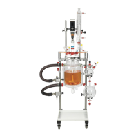
Lower the T-beam support brace onto all three
support rods. The rounded top of the central
support rod should be just visible above the central
hole in the brace.
Hand-tighten the three locking knobs.
❖ The T-beam support brace’s sole function is to add stability to and maintain alignment of the
framework.
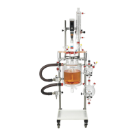
Slide a safety stop collar onto each of the outer
support rods. These will support the stirrer support
I-beam.
When they are in approximately the correct
position, hand-tighten both locking knobs.
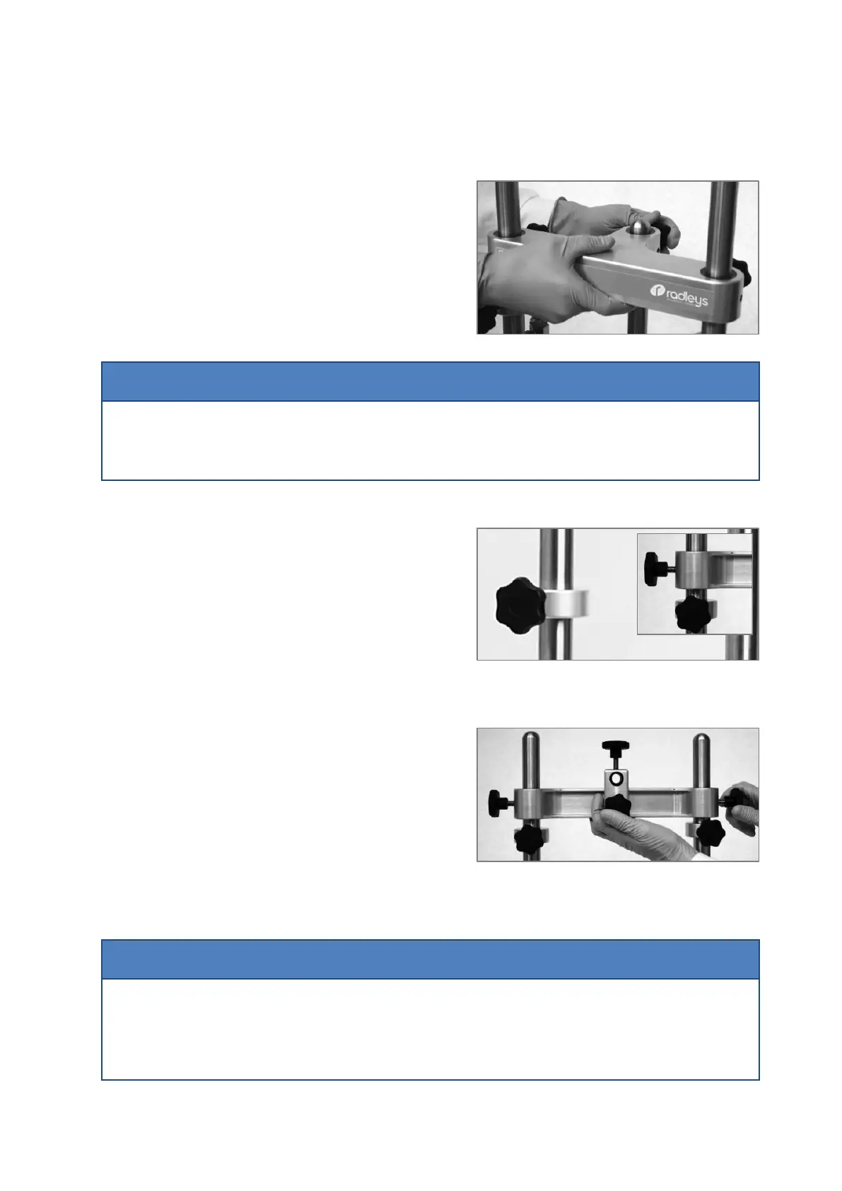
Now slide the stirrer support I-beam onto
the outer support rods, ensuring the two knobs on
the central sliding boss are pointing upwards and to
the front. Once it is in the correct position, secure it
by hand-tightening the two outer locking knobs.
Adjust the safety stop collars so that they are
located directly under the I-beam and retighten the
locking knobs.
❖ The stirrer support I-beam is designed to support an overhead stirrer, and features precision bore
slide bearings enabling smooth height adjustment, offering maximum user flexibility in
configuring the system.
 Loading...