EasyManuals Logo

Raisecom RC3000 PCM User Manual

Raisecom RC3000 PCM
86 pages
To Next Page IconTo Next Page
To Previous Page IconTo Previous Page
Page #24 background imageLoading...
Page #24 background image
Raisecom Technology Co., Ltd
23
find problems in time.
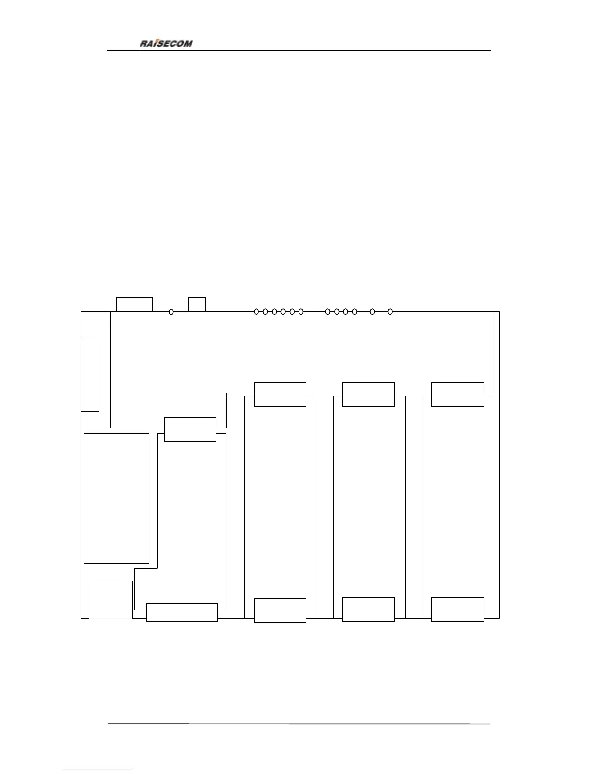
MPU control modue: this module is the system controller; once powered on it will check
the data saved in the memory, if the data is valid MPU will configure device according to
saved data, otherwise it will generate default data according to hardware status and set
the default data to RC7850 for cross connect, and than system will work normally. In
normal work status MPU will collect information of line-board module, user-board module,
RC7850 module and alarm continuously and control all the modules. MPU also answers
user queries, receives configuration operations, saves new configuration in memory
memory module and displays system information and alarms.
Architecture of RC3000 is as figure16:
Management
Power
su
pp
l
y
User
interface
card
Up-link
card
中心复
接单元
Power
supply
Center
m
u
lti
p
l
e
x
er
Up-link card
User interface
card
User interface
card
User interface
card
User interface
card
User interface
card
Alarm and system indicator
li
g
ht
s
CONSOLE
Fan
Figure 16

Table of Contents

Questions and Answers:

Question and Answer IconNeed help?

Do you have a question about the Raisecom RC3000 PCM and is the answer not in the manual?

Raisecom RC3000 PCM Specifications

General IconGeneral
BrandRaisecom
ModelRC3000 PCM
CategoryMultiplexer
LanguageEnglish

Related product manuals