Raisecom Technology Co., Ltd
37
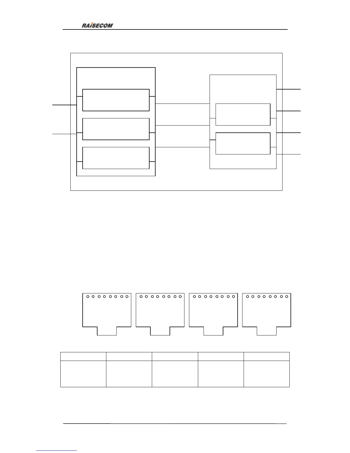
Fundamental structure of RC3000-SUB-DM2:
7.6. RC3000-SUB-DM4 audio relay card explanation
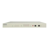
RC3000-SUB-DM2 is a 4W audio relay card with E&M signal, used for signal and voice
transmission between offices. There totally 8 channels decided by hardware,
unchangeable. Two RJ45 interfaces make up of the 8 channels (each RJ45 interface has
four channnels). Definition of RJ45 interface is as follows:
Channel 1 2 3 4
Pins
RJ45-1
1TA, 2TB
3RA, 4RB
6E, 7M
RJ45-2
1TA, 2TB
3RA, 4RB
6E, 7M
RJ45-3
1TA, 2TB
3RA, 4RB
6E, 7M
RJ45-4
1TA, 2TB
3RA, 4RB
6E, 7M
Note: 1TA and 2TB is 2-wire voice Tx, 3RA and 4RB is 2-wire voice Rx, 6E is E signal Rx
and 7M is M signal Tx.
Voice channel control module
Multiplexing module
Voice channel
interface
Bus
interface
Multiplexing
bus
Control bus
Multiplexing bus
process module
Control bus process
module
Voice input &
output
Signal input &
output
Control of
channel output
2W & 4W balance
module
Voice D/A converter
E & M signal process
module
Figure 28
1 2 3 4 5 6 7 8
1 2 3 4 5 6 7 8
RJ45-1 RJ45-2
1 2 3 4 5 6 7 8
1 2 3 4 5 6 7 8
Figure 29
RJ45-3 RJ45-4