Raisecom Technology Co., Ltd
36
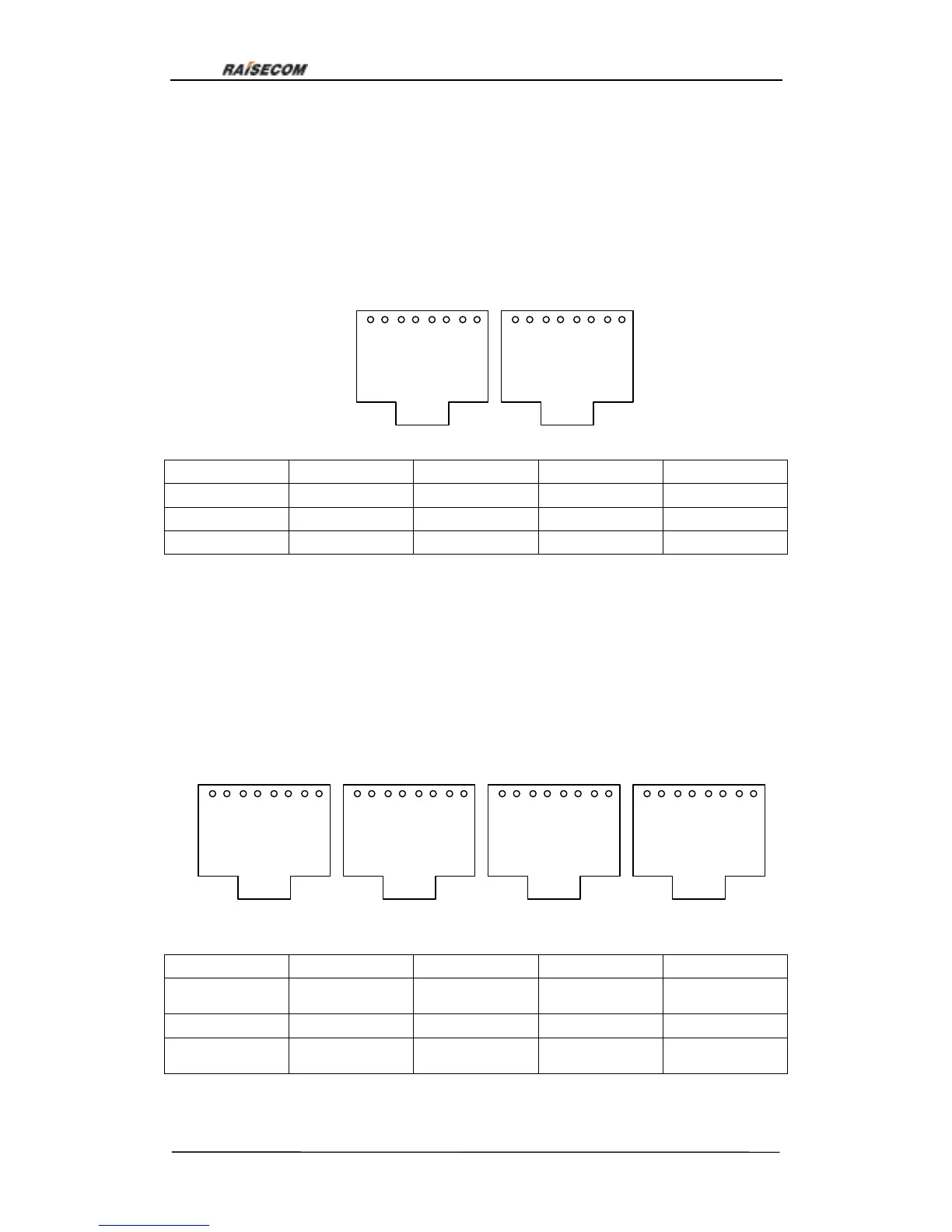
7.4. RC3000-SUB-DSO user-board explanation
RC3000-SUB-DSO is a customized hybrid card of FXS and FXO, there can be N FXS
interfaces and M FSO interfaces (M, N can be 0, and M+N=8). There totally 8 channels
decided by hardware, unchangeable. Two RJ45 interfaces make up of the 8 channels
(each RJ45 interface has four channnels). Definition of RJ45 interface is as follows:
Channel 1 2 3 4
Pins RJ45-1 1A,2B RJ45-1 3A,4B RJ45-1 5A,6B RJ45-1 7A,8B
Channel 5 6 7 8
Pins RJ45-2 1A,2B RJ45-2 3A,4B RJ45-2 5A,6B RJ45-2 7A,8B
7.5. RC3000-SUB-DM2 audio relay card explanation
RC3000-SUB-DM2 is a 2W audio relay card with E&M signal, used for transmission of
signal and voice between offices. There totally 8 channels decided by hardware,
unchangeable. Two RJ45 interfaces make up of the 8 channels (each RJ45 interface has
four channnels). Definition of RJ45 interface is as follows:
Channel 1 2 3 4
Pins
RJ45-1
1A, 2B, 3E, 4M
RJ45-1
5A, 6B, 7E, 8M
RJ45-2
1A, 2B, 3E, 4M
RJ45-2
5A, 6B, 7E, 8M
Channel
5 6 7 8
Pins
RJ45-3
1A, 2B, 3E, 4M
RJ45-3
5A, 6B, 7E, 8M
RJ45-4
1A, 2B, 3E, 4M
RJ45-4
5A, 6B, 7E, 8M
Note: A and B is 2-wire channel voice, E is E signal Rx and M is M signal Tx.
1 2 3 4 5 6 7 8
1 2 3 4 5 6 7 8
Figure 26
RJ45-1 RJ45-2
1 2 3 4 5 6 7 8
1 2 3 4 5 6 7 8
RJ45-1 RJ45-2
1 2 3 4 5 6 7 8
1 2 3 4 5 6 7 8
Figure 27
RJ45-3 RJ45-4