Raisecom Technology Co., Ltd
33
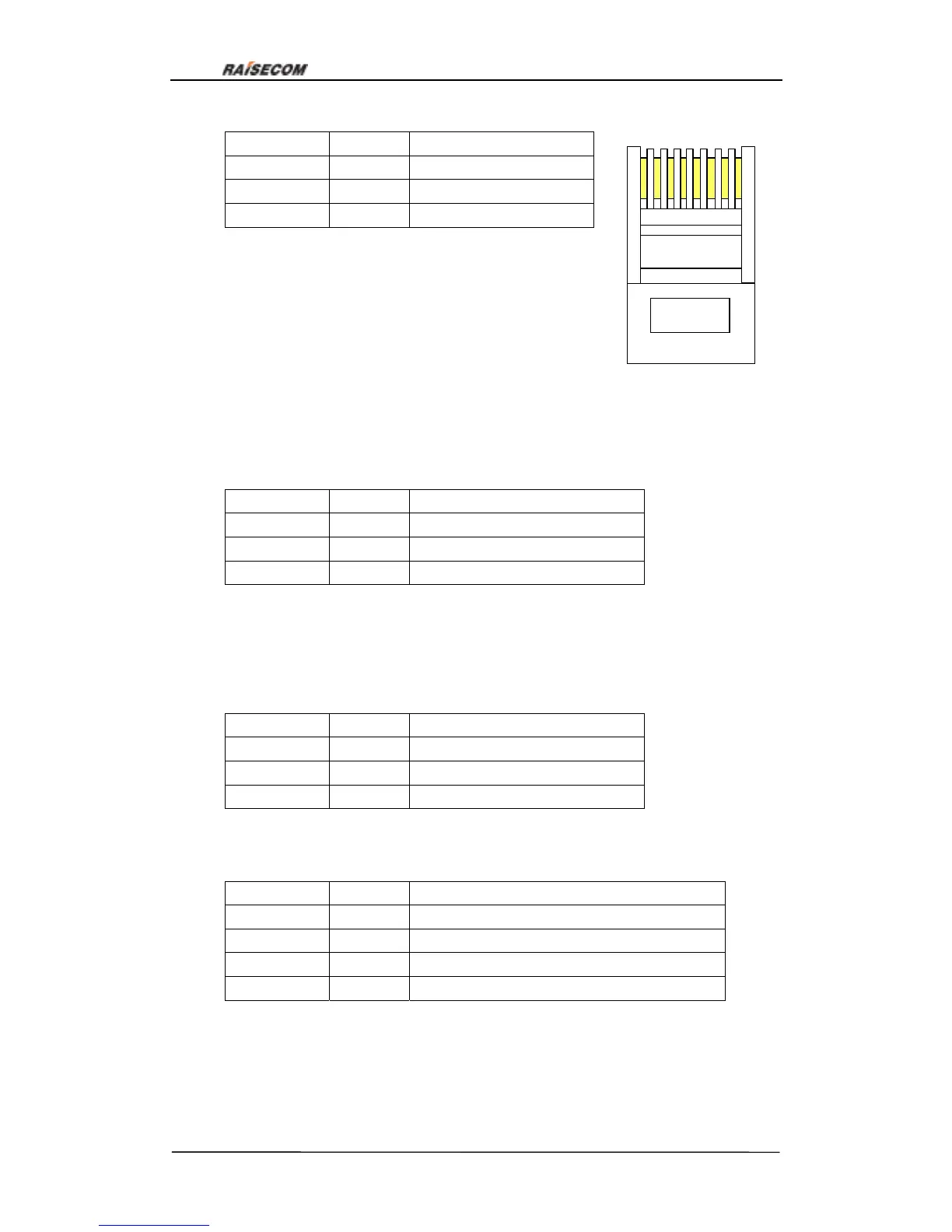
Pin number Signal Explanation
3 RXD Rx of RC3000
7 TXD Tx of RC3000
4,8 GND Ground of RC3000
b.LINK UP definition:
Network management interface LINK UP is RC45 interface and standard RC232 voltage:
Signaling and Pinouts:
Pin number Signal Explanation
3 RXD Rx of RC3000
7 TXD Tx of RC3000
4,8 GND Ground of RC3000
c. LINK DOWN definition:
Network management interface LINK DOWN is RC45 interface and standard RC232
voltage:
Signaling and Pinouts:
Pin number Signal Explanation
3 TXD Rx of RC3000
7 RXD Tx of RC3000
4,8 GND Ground of RC3000
d. Definition of balanced RC3000-4E1 E1 interface:
Balanced E1 interface is RJ45 interface, and the Signaling and Pinouts are:
Pin number Signal Explanation
1 OUT+ Positive Tx of balanced E1 interface
2 OUT- Negative Tx of balanced E1 interface
5 IN+ Positive Rx of balanced E1 interface
6 IN- Negative Rx of balanced E1 interface
Figure 21
1 2 3 4 5 6 7 8