Raisecom Technology Co., Ltd
67
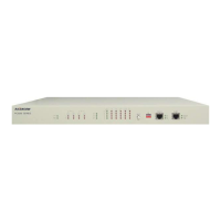
In this topology, the configuration of each device is as follows;
Device 1: Set the second bit of DIP-switches ON, and others OFF; use two E1, time slot
0 and single E1 direction.
Device 2: Set all DIP-switches OFF; use two E1s, time slot 0 and double E1 direction.
Device 3: Set all DIP-switches OFF; use two E1s, time slot 0 and single E1 direction.
If your configuration of any of the three devices is not same as above, there will be
device that cannot be managed. (Attention: 0nly device 2 is configured as double E1
direction).
Figure 44
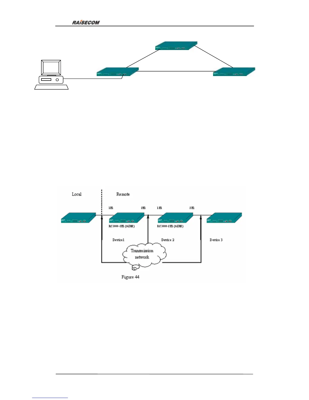
Here is a more complex topology:
In this topology connect RS232 serial interface of PC with LINK UP interface of device 1,
device 1 and device 2, device 2 and device 3, device 3 and device 4, device 4 and
device 5 are connected through E1 cable, and connect LINK DOWN interface of device 2
with LINK UP interface of device 4 to realize remote network management connection.
The configuration of each device is as follows:
Device 1: Set the second bit of DIP-switches ON, and others OFF; use one E1, time slot
0 and single E1 direction.
Device 2: Set all DIP-switches OFF; use two E1s, time slot 0 and double E1 direction.
Device 3: Set all DIP-switches OFF; use one E1, time slot 0 and single E1 direction.
Device 4: Set the second bit of DIP-switches ON, and others OFF; use one E1, time slot
Figure 43
RC3000-2E1
RC3000-2E1
1E1
2E1
Device 1
Device 2
Device 3
RC3000-2E1
1E1
1E1
2E1
2E1