MTR221/A - MTR221/A DHHS
MANUALE ISTRUZIONI / INSTRUCTION MANUAL
Modello/Model R221/A - R221/A DHHS
OPTIONAL ITEMS
44
R221/A - R221/A DHHS - Optional Items
Ralco srl
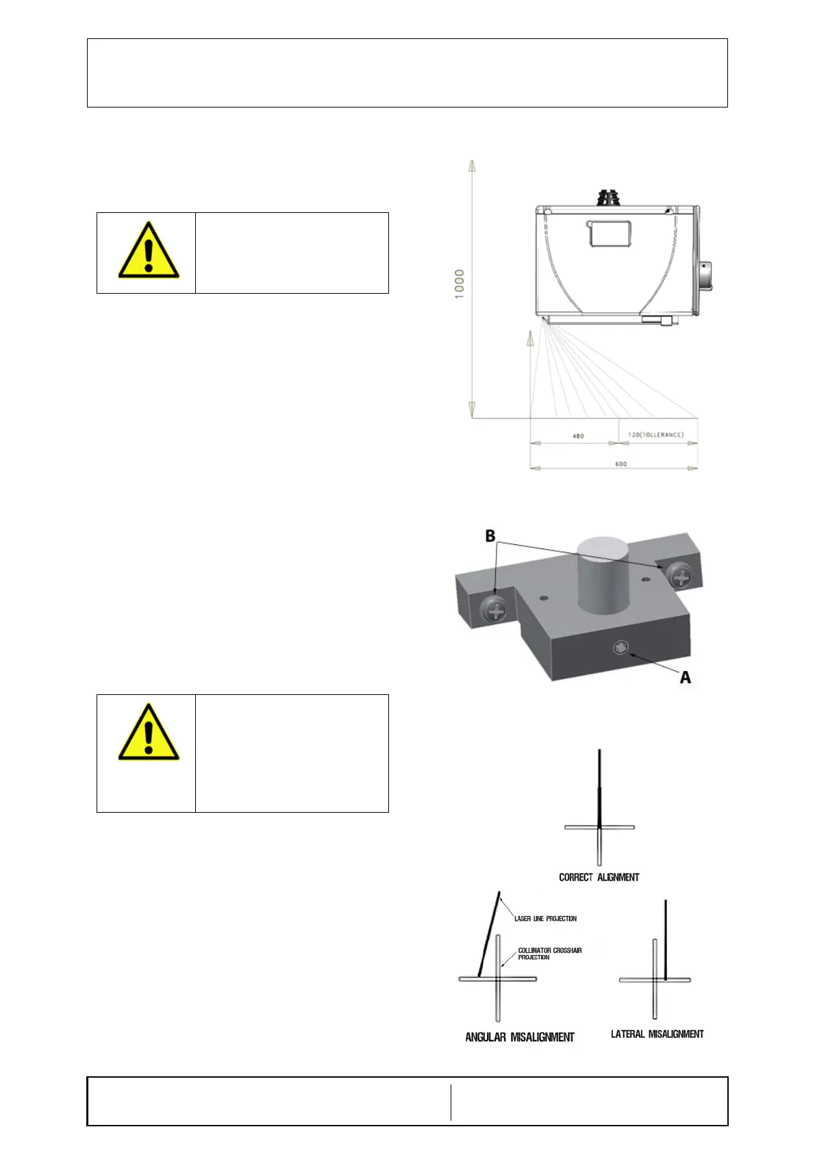
RO 242/1 Single Laser
The collimator laser is classified as Class 2 (1 m W
- wavelength = 645 mm); used for collimator/image
receptor center alignment, see Fig. Laser Line.
Laser Adjustment
• Remove part of the cover to access the point of
adjustment, see Chapter- C
OVER REMOVAL.
• The line is to fall on a perpendicular cross-line
on the plastic anti-dust panel near the collimator
controls, see Fig. Laser Line.
• Adjust the position of the line by rotating or
moving the base of the laser system.
• To rotate the laser system, loosen the
Allen screw A, see Fig. Laser
Adjustment.
• Tighten the Allen screw when the laser
beam falls on or is parallel to the bisector
line drawn on the anti-dust panel.
• Shift the laser system by loosening the two B
screws holding the laser system base to the
beam limiting device front plate.
• Move the base until the laser beam falls
over the perpendicular bisector line on the
anti-dust panel, see Fig. Laser
Alignment.
• Tighten the two B screws.
Substitution
• Disconnect supply.
• Remove the cover, see Chapter- C
OVER
R
EMOVAL.
• Unscrew the fixing Allen screws A, see Fig.
Laser Adjustment.
• Disconnect the timer cables from the terminal
board - white 0 V, red 5 V.
• Remove the laser and substitute with an
identical item.
• Tighten the screws.
CAUTION: CLASS 2 LASER SYSTEM
DO NOT STARE INTO THE BEAM.
D
O NOT APPLY EXCESSIVE FORCE
TO THE SCREW. THE LASER SHELL
IS IN PLASTIC AND EXCESSIVE
PRESSURE COULD CRACK THE
PLASTIC AND POSSIBLY SHORT-
CIRCUIT THE LASER.
Fig. Laser Line
Fig. Laser Adjustment
Fig. Laser Alignment
 Loading...