MTR221/A - MTR221/A DHHS
MANUALE ISTRUZIONI / INSTRUCTION MANUAL
Modello/Model R221/A - R221/A DHHS
OPTIONAL ITEMS
51
R221/A - R221/A DHHS - Optional Items
Ralco srl
RO 339 Double Laser for Optical SID
The collimator has two lasers which serve for the optical definition of the prefixed SID. The
lasers are mounted behind the front panel. Two laser lines must measure 60 cm (+/-1) at 1 m
(+/- 0.5 cm) and projected at 10 cm (+/-1) from the centre of the light/X-ray field. The projection
of a single line signifies that the two lines overlap and consequently the lasers are correctly
focussed at the SID set. The projection of two laser lines signifies the SID value has not be
entered correctly. See fig. Laser Line.
Laser Adjustment
• Remove part of the cover to access the point of adjustment, see Chapter- C
OVER
R
EMOVAL.
• The line is to fall on a perpendicular cross-line on the plastic anti-dust panel near the
collimator controls, see Fig. Laser Line.
• Adjust the position of the line by rotating or moving the base of the laser system.
• To rotate the laser system, loosen the Allen screw A, see Fig. Laser Adjustment.
• Tighten the Allen screw when the laser beam falls on or is parallel to the bisector line
drawn on the anti-dust panel.
• Shift the laser system by loosening the two B screws holding the laser system base to the
beam limiting device front plate.
• Move the base until the laser beam falls over the perpendicular bisector line on the
anti-dust panel, see Fig. Laser Adjustment.
• Tighten the screws B.
Substitution
• Disconnect supply.
• Remove the cover, see Chapter- C
OVER REMOVAL.
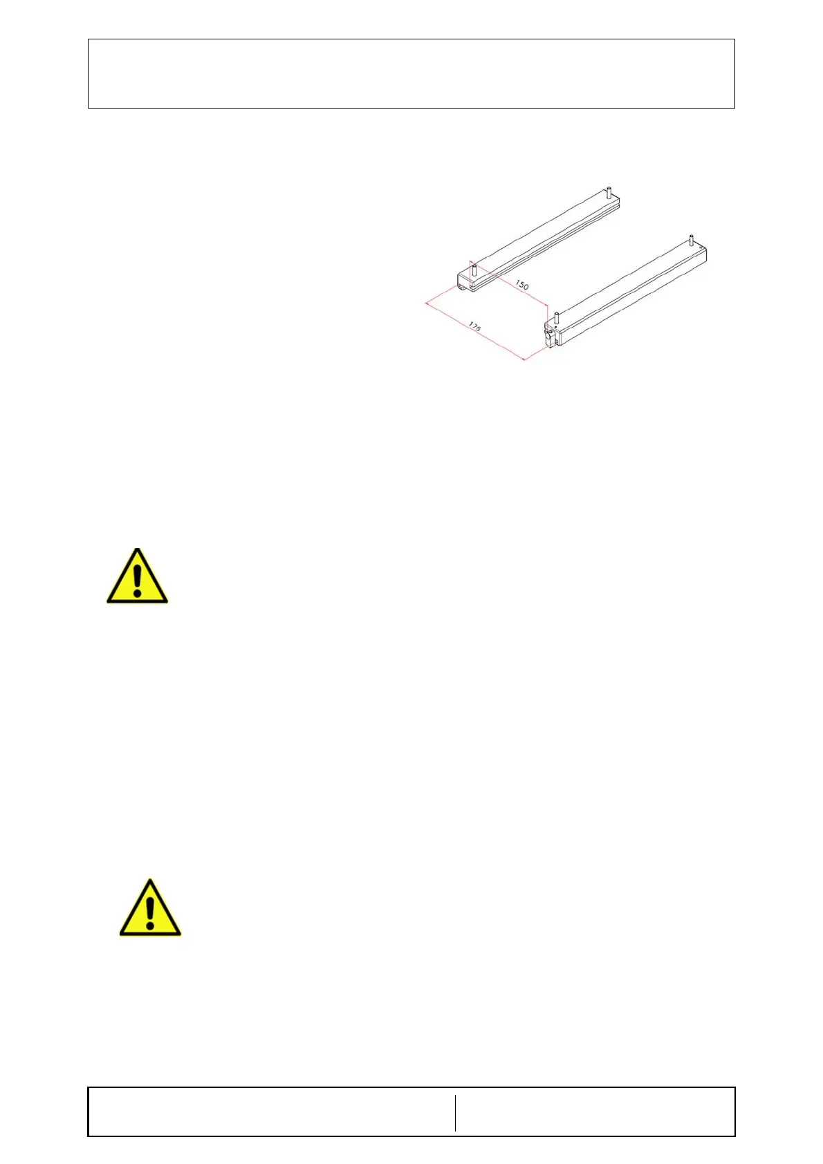
RO 336 Spacer Guides
Pair of aluminium rail guides designed for an
ionisation chamber with different dimensions
to standard chamber and to allow the
insertion of other accessories.
CAUTION: CLASS II LASER SYSTEM DO NOT STARE
INTO THE BEAM.
D
O NOT APPLY EXCESSIVE FORCE
TO THE SCREW. THE LASER SHELL
IS IN PLASTIC AND EXCESSIVE
PRESSURE COULD CRACK THE
PLASTIC AND POSSIBLY
SHORT-CIRCUIT THE LASER.
 Loading...