SECTION 2 - GUIDE RAILS AND CROSS BRACES.
Page 2-3
Rev 1A – Oct. 2003
2.3
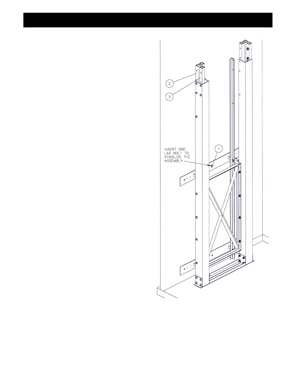
Stand lower guide rail assembly against supporting wall.
Measure from each guide rail to the nearest wall, the
distance should be equal. If you are unable to keep the
guide rails an equal distance from both walls for the entire
travel distance then pick a wall (the one with the doors) and
make sure the guide rails run parallel to that wall for the
entire travel distance. Install ONE lag bolt into the top wall
mounting bracket to stabilize the assembly (FIG. 3), leave
all of the other bolts loose.
Figure 3. Lower guide rail installation, looking from
in front of the guide rails.
NOTE:
MATERIAL LIST PART #
1. Lag bolt 1/4 x 3 long (wood wall), or
concrete block lag bolt 1/4 X 2 1/4
(concrete block wall).
PGAGF082
or
PGAGF083
2. Guide rail connector section (double)
Change required Conn. Section with
welded lock nuts
FFBUG013
3. Guide rail connector section (single) FFGUG015