Preparation for Use
R&S
®
EB500
9Getting Started 4072.8432.02 ─ 04
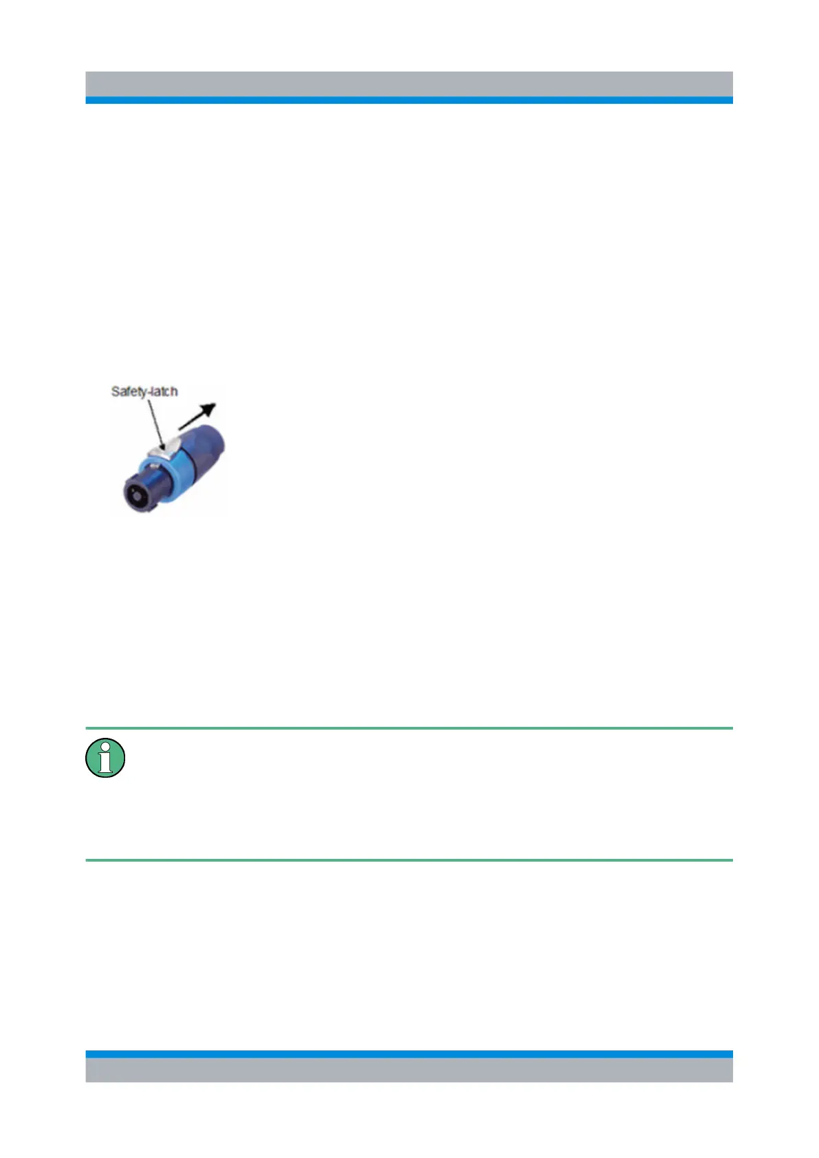
Installing the connector:
1.
Insert the Speakon® NL4FX connector into socket X1 on the rear panel.
2. Turn the connector clockwise until it is locked in place and secured by the safety
latch.
Removing the connector:
1. Press and chuck back the safety latch of the Speakon® NL4FX connector.
2. Turn the connector counterclockwise and withdraw it.
Fig. 1-1: Speakon® NL4FX
1.2.5.2 Connecting to the DC Source
The R&S EB500
is connected to an external 10 VDC to 32 VDC source (e.g. battery)
via connector X1 on the rear panel. Recommended connector: Neutrik® Speakon®
NL4FX, see chapter 1.2.5.1, "Connecting to the Power Adapter", on page 8.
DC supply voltage
Make sure that the available supply voltage is between 10 V and 32 V.
Observe correct voltage polarity when connecting. Incorrect polarity may blow
the fuse on the DC converter inside the R&S EB500 or damage the
R&S EB500.
Setup