28
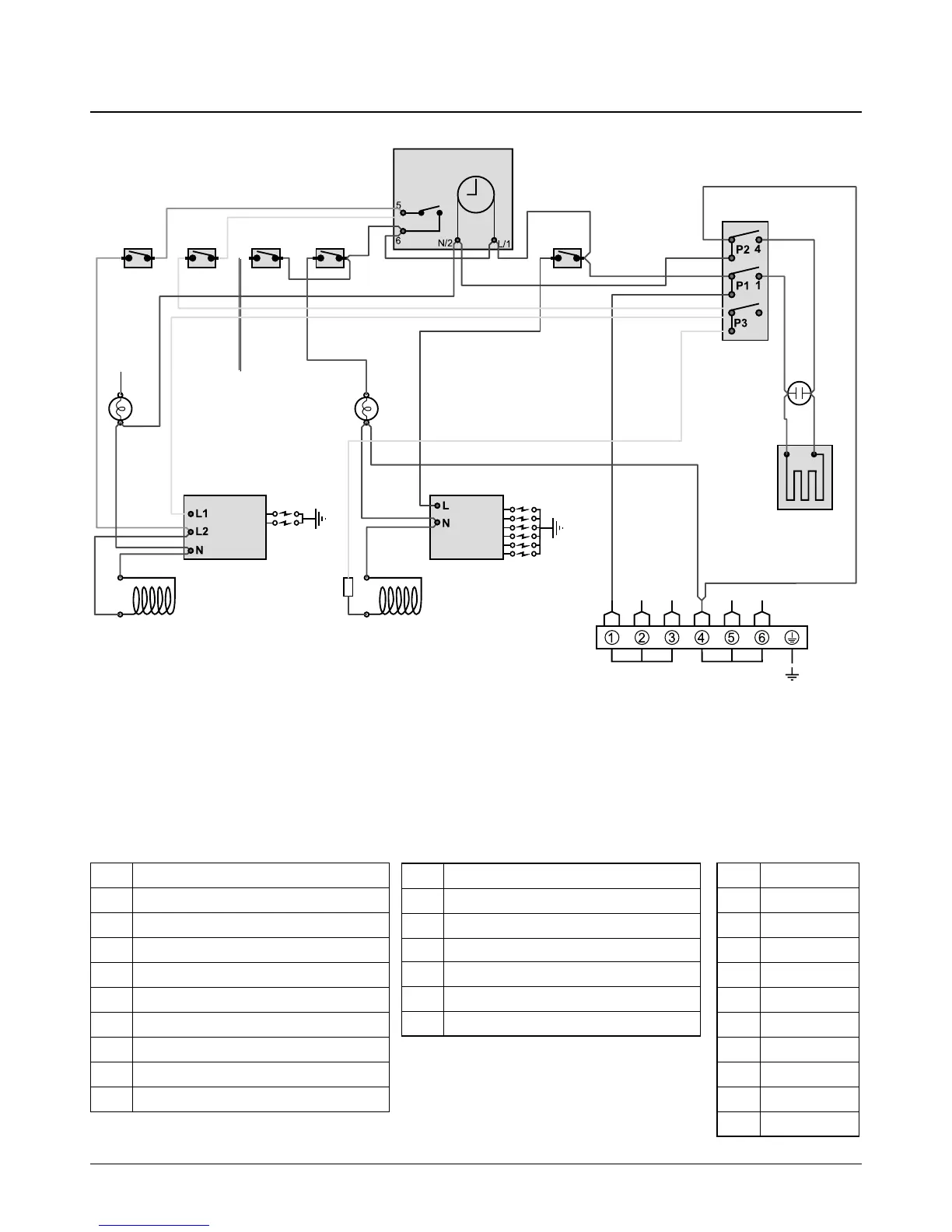
8. Circuit Diagram
LN
E
or
y
br
br brbr
br
br
br
v
br
w
y
y
r
oror
w
b
b
y
or
b
br
br
b
y
br
b
b
v
br
bb
r
b
b
br
br
br
y
y
y
r
b
b
b
r
r
bb
A1 A2 B1 B3
C
D1
F
A3
G
A4
D2
A5
B2 B4
H
Key
The connections shown in the circuit diagram are for single-phase. The ratings are for 230 V 50 Hz.
Code Colour
b Blue
br Brown
bk Black
or Orange
r Red
v Violet
w White
y Yellow
g/y Green/yellow
gr Grey
Code Description
A1 Right-hand oven thermostat switch
A2 Left-hand oven thermostat switch
A3 Oven spark generator
A4 Right-hand oven solenoid/FSD
A5 Left-hand oven solenoid/FSD
B1 Right-hand oven light switch
B2 Right-hand oven light
B3 Left-hand oven light switch
B4 Left-hand oven light
Code Description
C Clock
D1 Ignition switch
D2 Hotplate & grill spark generator
F Warmer plate switch
G Warmer
H Neon