26
Legend
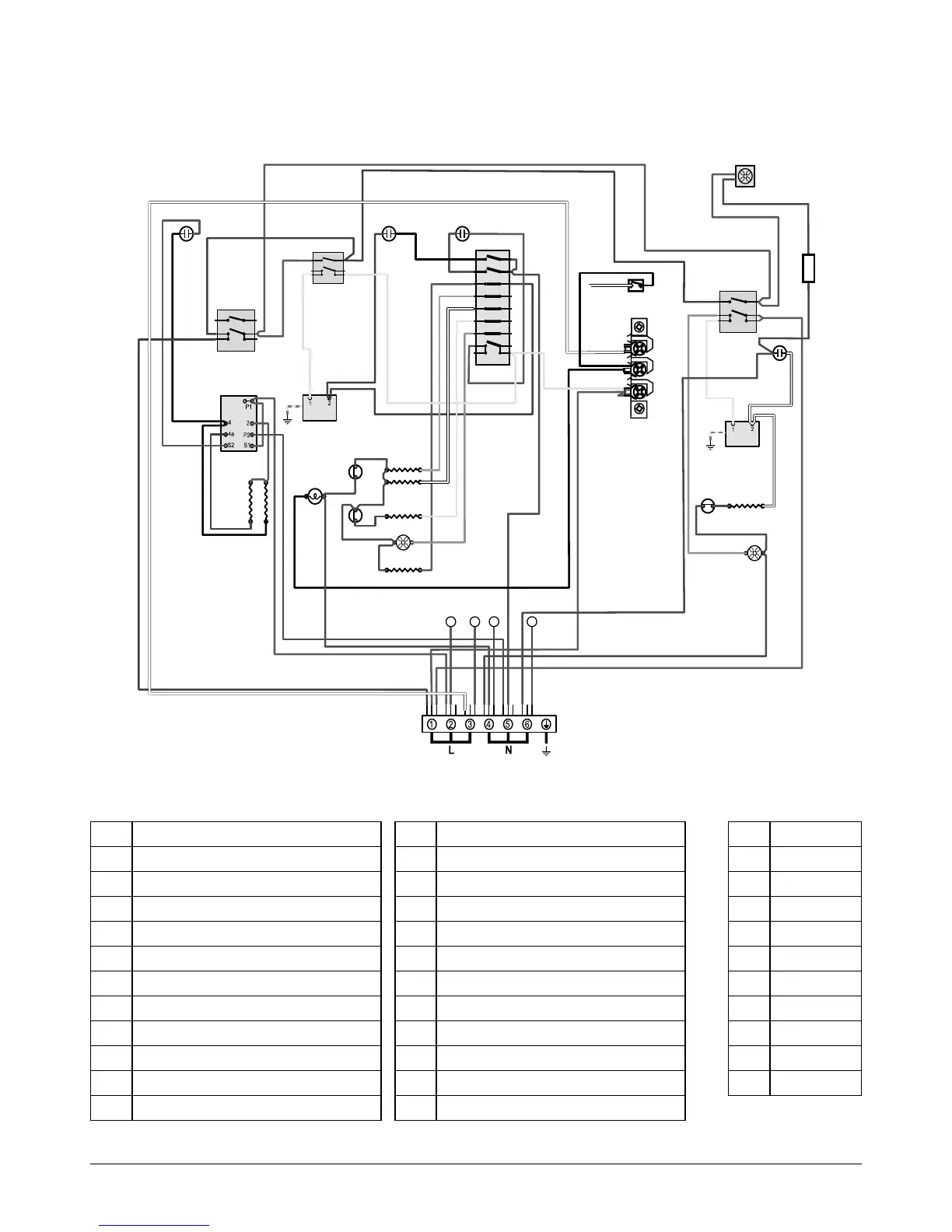
The connections shown in the circuit diagram are for single-phase. The ratings are for 230 V 50 Hz.
Oven Circuit Diagram
Code Description
A1 Grill front switch
A2 Grill energy regulator
A3 Grill elements
B1 Left-hand oven front switch
B2 Left-hand oven thermostat
B3 Left-hand oven top element (outer)
B4 Left-hand oven top element (inner)
B5 Left-hand oven fan element
B6 Left-hand oven fan
B7 Left-hand oven base element
B8 Left-hand multi-function switch
Code Description
C Inline connector
TB Internal terminal block
D1 Right-hand oven front switch
D2 Right-hand oven thermostat
D3 Right-hand oven element
D4 Right-hand oven fan
F1 Oven light switch
F2 Oven light
G Neon
H Thermal cut-out
I Cooling fan
Code Colour
b Blue
br Brown
bk Black
or Orange
r Red
v Violet
w White
y Yellow
g/y Green / Yellow
gr Grey
P028728
6
P6
5 P5
4
P4
7 P7
8 P8
2
P2
1 P1
3 P3
P095199
1
2
P2
P1
E
P095199
1
2
P2
P1
v
P095199
1
2
P2
P1
12 54
g/y
y
bk r
b
b
r
or
y
w
g/y
br
gr
or
br
y
w
b
y
w
r
br
b
v
v
y
r
y
y
bk
v
v
r
bk
b
v
v
br
br
bk
br
r
r
r
bk
b
bk
b
b
b
b
b
b
b
b
b
b
b
b
b
w
gr
y
r
or
b
r
v
w
bb w
b
b
or
br
v
b
b
bb b b
br
w
r
b
v
b
r
r
y
v
br
r
r
bk
Red boot
Red boot
bk
w
w
w bk
Red boot
Red boot
Red boot
Red boot Red boot
bk
br
A2
B1
A3
B3
B4
B2
B5
B6
B7
D2
G
D1
D3
B8
D4
F1
G
H
G
H
F2
G
H
I
A1
C
TB