Code Description
A1 Grill front switch
A2 Grill energy regulator
A3 Grill element left-hand side
A4 Grill element right-hand side
B1 Left-hand multi-function oven thermos tat
B6 Left-hand multi-function oven fan element
B7 Left-hand multi-function oven fan
C Clock
D1 Right-hand fan oven thermostat
Code Description
F2 Ignition spark generator
G1 Ceramic hob energy regulator
G2 Rear Ceramic hob element
G3 Front Ceramic hob element
H1 Oven light switch
H2 Oven light
I Thermal cut-out
J Neon
K Cooling fan
M1 Proving draw switch
M2 Proving draw energy regulator
M3 Proving draw element
Code Colour
b Blue
br Brown
bk Black
or Orange
r Red
b
b
b
b
b
b
b
b
b
b
b
b
b
b
b
b b
br
br
or
or
y
b
w
w
y
bk
b
bk
r
r
bk
r
v
v
br
br
bb
v
w
r
y
y
w
bk
or
w
bk
b
v
w
br
r
bk
w
r
bk
v
v
br
y
r
b
y
v
v
v
r
w
br
bk
y
r
bk
r
r
y
y
r
v
b
bk
bk
br
v
br
W3
Key
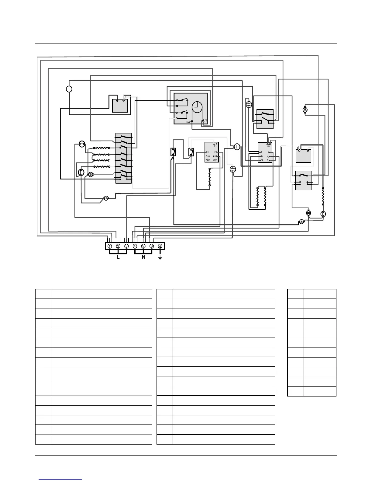
The connections shown in the circuit diagram are for single-phase. The ratings are for 230 V 50 Hz.
8. Circuit Diagram
Code Description
A1 Grill front switch
A2 Grill energy regulator
A3 Grill element left-hand side
A4 Grill element right-hand side
B1 Left-hand multifunction oven thermostat
B2 Left-hand multifunction oven control
B3 Left-hand multifunction oven base element
B4
Left-hand multifunction oven top element
(outer pair)
B5
Left-hand multifunction oven browning
element (inner pair)
B6 Left-hand multifunction oven fan element
B7 Left-hand multifunction oven fan
C Clock
D1 Right-hand fan oven thermostat
D2 Right-hand fan oven control
Code Description
D3 Right-hand fan oven element
D4 Right-hand fan oven fan
F1 Ignition switches
F2 Ignition Spark Generator
G1 Ceramic hob energy regulator
G2 Rear ceramic hob element
G3 Front ceramic hob element
H1 Oven light switch
H2 Oven light
I Thermal cut-out
J Neon
K Cooling fan
M1 Proving drawer switch
M2 Proving drawer energy regulator
M3 Proving drawer element
Code Colour
b Blue
br Brown
bk Black
or Orange
r Red
v Violet
w White
y Yellow
g/y Green/Yellow
gr Grey