BH-SERIES INSTALLATION, OPERATION AND SERVICE MANUAL
6 of 59
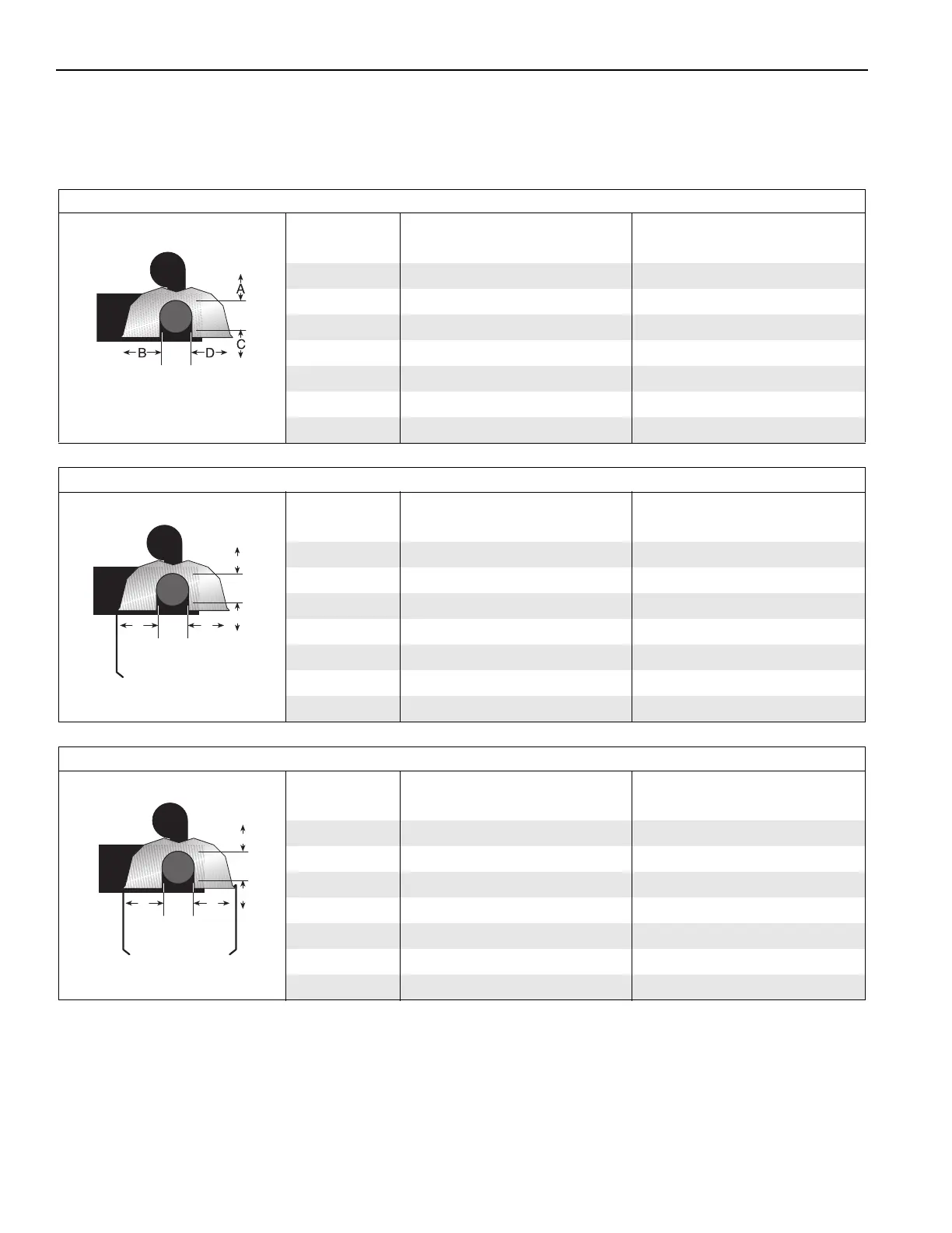
NOTE: 1. All dimensions are from the surfaces of all tubes, couplings and elbows.
2. Clearances B, C and D can be reduced by 50% after 25' (7.5 m) of tubing downstream
from where the burner and burner tube connect.
FIGURE 3: Standard Reflector
(inches) (centimeters)
Model ABCDABCD
BH-40 6 27 52 27 16 69 133 69
BH-60 6 35 62 35 16 89 158 89
BH-80 6 38 65 38 16 97 166 97
BH-100 6 40 70 40 16 102 178 102
BH-115/125 6 46 76 46 16 117 194 117
BH-140/150 6 50 79 50 16 127 201 127
BH-175/200 8 52 82 52 21 133 209 133
FIGURE 4: One Side Reflector
(inches) (centimeters)
Model ABCDABCD
BH-40 6 9 52 44 16 23 133 112
BH-60 6 9 62471623158120
BH-80 6 9 69 54 16 23 176 138
BH-100 6 9 76 59 16 23 194 150
BH-115/125 6 9 82 65 16 23 209 166
BH-140/150 6 9 85 69 16 23 216 176
BH-175/200 8 9 88 73 21 23 224 186
FIGURE 5: Two Side Reflectors
(inches) (centimeters)
Model ABCDABCD
BH-40 6 15 52 15 16 39 133 39
BH-60 6 23 65 23 16 59 166 59
BH-80 6 25 71 25 16 64 181 64
BH-100 6 277727166919669
BH-115/125 6 32 83 32 16 82 211 82
BH-140/150 6 35 87 35 16 89 221 89
BH-175/200 8 40 91 40 21 102 232 102