33
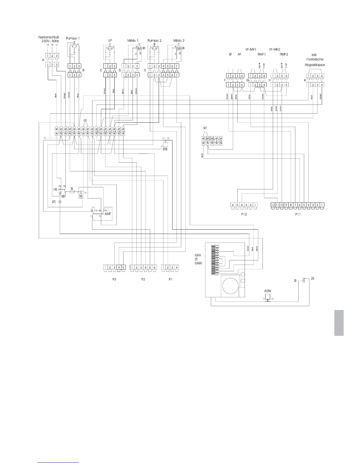
15 Circuit diagram
AA
BB
English
A,B,C,... Marking of cables MiMo AC -motor
a open N Neutral
AF External sensor PE Mains earth
AMT Auto/man/TÜV switch P1...P12 indication of control plugs
AÜW Waste gas flue control RMF Room sensor, comfortmatic, RFFT
GFA Ignition automat RT Room thermostat
GMV Magnetic valve SF Boiler sensor
HS Main switch Si Fuse 6.3A inertial
IS Ionization electrode STB Safety temperature limiter
KF Boiler sensor STL Fault lamp
L Power line 230V, 50Hz TR Temperature control
LP Feed pump VF-MK Water flow sensor mixing system
L1 Mains phase 230V, 50Hz z close
M Motor ZE Ignition electrode
MA Motor driven waste gas shutter Room thermostat ZT Ignition transformer
(only with system without rapidomatic
®
boiler control)
motorische
Abgasklappe