EasyManua.ls Logo

Raritan PM Series - User Manual

Raritan PM Series
20 pages
Print Icon
To Next Page IconTo Next Page
Loading...
Power Meter Quick Setup Guide
1
QSG
-PMM-1A-v3.3.10-E 255-64-0004-00
PM Series Power Meter
Safety Information
DANGER!
HAZARD OF ELECTRIC SHOCK, EXPLOSION, OR ARC FLASH
Follow safe electrical work practices. See NFPA 70E in the USA, or applicable local codes.
This equipment must only be installed and serviced by qualified electrical personnel.
Read, understand and follow the instructions before installing this product.
Turn off all power supplying equipment before working on or inside the equipment.
Any covers that may be displaced during the installation must be reinstalled before powering the unit.
Use a properly rated voltage sensing device to confirm power is off.
DO NOT DEPEND ON THIS PRODUCT FOR VOLTAGE INDICATION
Failure to follow these instructions will result in death or serious injury.
NOTICE
This product is not intended for life or safety applications.
Do not install this product in hazardous or classified locations.
The installer is responsible for conformance to all applicable codes.
Mount this product inside a suitable fire and electrical enclosure.
CAUTION
RISK OF EQUIPMENT DAMAGE
This product is designed only for use with 0.33V output current transducers (CTs).
DO NOT USE CURRENT OUTPUT (e.g. 5A) CTs ON THIS PRODUCT.
Failure to follow these instructions can result in overheating and permanent equipment damage.
For use in a Pollution Degree 2 or better environment only. A Pollution Degree 2 environment must control conductive pollution and
the possibility of condensation or high humidity. Consider the enclosure, the correct use of ventilation, thermal properties of the
equipment, and the relationship with the environment. Installation category: CAT II or CAT III
Provide a disconnect device to disconnect the meter from the supply source. Place this device in close proximity to the equipment and
within easy reach of the operator, and mark it as the disconnecting device. The disconnecting device shall meet the relevant
requirements of IEC 60947-1 and IEC 60947-3 and shall be suitable for the application. Disconnecting fuse holders can be used in the
USA and Canada. Provide overcurrent protection and disconnecting device for supply conductors with approved current limiting
devices suitable for protecting the wiring.
If the equipment is used in a manner not specified by the manufacturer, the protection provided by the device may be impaired.
This symbol indicates an electrical shock hazard exists.
Documentation must be consulted where this symbol is used on the product.
Equipment Maintenance and Service
WARNING! This equipment must only be installed by qualified electrical personnel. This product contains no user serviceable parts.
Do not open, alter or disassemble this product. All repairs and servicing must be performed by Raritan authorized service personnel.
Failure to comply with this warning may result in electric shock, personal injury and death.
Raritan
400 Cottontail Lane, Somerset, NJ 08873 USA
QUICK SETUP GUIDE
PMC-1000, PMC-1001, PMM-1000, PMB-1960
Question and Answer IconNeed help?

Do you have a question about the Raritan PM Series and is the answer not in the manual?

Overview

The Raritan PM Series Power Meter is a modular power metering solution designed for monitoring power consumption in various electrical environments. The series includes three main components: the PMM (Power Meter Module), PMB (Power Meter Branch Monitor), and PMC (Power Meter Controller).

Function Description:

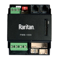
The PMM is a 3-phase power meter that provides neutral and earth current monitoring. It can function as a standalone unit or integrate with a PMB for more granular monitoring.

The PMB is a 96-channel branch circuit monitor that plugs directly into a PMM. When combined, a PMM+PMB configuration monitors both the main panel board and individual branch circuits.

The PMC acts as the central power meter controller. A single PMC can manage up to 70 PMMs or 8 PMM+PMB combinations. Interconnection between modules is achieved using standard shielded CAT-5 cable. The system is designed with redundant power, ensuring continued operation as long as one or more PMMs remain powered.

The PM series power meters are designed for ease of use, featuring current transducers (CTs) with built-in burden resistors that can be snapped onto live wires without damage. CT orientation is not critical, as the meter automatically corrects polarity for any CT installed backward. CT connections are made close to branch circuits using multi-conductor wiring harnesses with labeled wire-pairs and keyed connectors.

Important Technical Specifications:

Voltage Measurement Inputs:

  • Input Range: 90-277VLN, 156-480VLL (for models with field wiring terminals; factory-installed line-cords may have different ratings).
  • Phase to Ground: 277V
  • Measurement Category: CAT III, Pollution Level 2
  • Frequency: 47-63 Hz
  • Input Impedance: 10MΩ

Current Measurement Inputs:

  • Input Range: 0-400mV
  • Input Impedance: 10k
  • CT Type: Voltage Output = 333mV at rated current
  • CT Rated Current: 1-1200A

Meter Measurement Accuracy:

  • Active Power & Energy: 0.5% (IEC 62053 Class .5, EN 50470-3 Class C)
  • Reactive Power & Energy: 2%
  • RMS Voltage & Current: 0.2%
  • Frequency: 0.1%
  • Sample Rate: 64x AC frequency (phase locked)
  • Measurement Update Rate: 3 seconds (IEC 61000-4-30 Class S)

Power Requirements:

  • Voltage: 90-240V
  • Current: 0.2A
  • Overvoltage Category: CAT III, Pollution Level 2
  • Frequency: 47-63 Hz

Mechanical:

  • Terminal Block Screw Torque: 0.37 ft-lb (0.5Nm) to 0.44 ft-lb (0.6Nm)
  • Terminal Block Wire Size: 14-24AWG (.5-1.6mm)
  • Terminal Wire Temperature Rating: > 75 degree C
  • DIN Rail: T35 (35mm)

Environmental:

  • Operating Temperature: 0-60°C
  • Operating Humidity: 5-85%RH
  • Operating Elevation: 0-3000m
  • Pollution Degree: Designed for use in a Pollution Degree 2 or better environment, requiring control of conductive pollution and humidity.

Conformance:

  • Safety: UL/EN 61010-1
  • EMC/EMI: EN61326-1, FCC Part 15 Class A

Usage Features:

PMM Connectors and Controls:

  • Voltage measurement: Terminal block for voltage inputs.
  • Power: Power input terminals.
  • Meter Bus Connectors: RJ45 ports for connecting to the PMC and other PMMs in a daisy-chain.
  • Meter Bus Terminator Switch: Used to terminate the meter bus at the ends of a daisy chain.
  • Multi-conductor cable CT ABCNE connector: Keyed connector for CT inputs.
  • Meter ID configuration switch: For assigning unique IDs to meters.
  • Expansion port: Connects PMM to PMB.

PMB Connectors:

  • Multi-conductor cable CT connectors (1-8): Keyed connectors for individual branch circuit CTs.
  • Expansion port: Connects PMB to PMM.

PMC iX6 Connectors and Controls:

  • MODBUS RTU isolated RS-485: For Modbus communication.
  • Meter bus connector (to PMM): RJ45 port for connecting to the PMM daisy chain.
  • Meter bus terminator switch: For terminating the meter bus.
  • 10/100 base-t Ethernet: Network port for web interface access.
  • Feature port (Raritan asset strip): For connecting Raritan asset strips.
  • Sensor port (temperature, humidity, etc.): For environmental sensors.
  • USB A & B: For flash drives, Wi-Fi, serial port.
  • RS-232: For terminal CLI or modem.
  • Pin-hole access reset button: For resetting the device.
  • LCD: Displays meter readings, settings, and configuration.
  • Keypad: For navigating the LCD menu.

DIN Rail Mounting:

PMM and PMB modules snap onto a 35mm DIN rail. Expansion connectors are used to link PMM and PMB modules. It is critical to disconnect all power sources before hot-plugging the expansion port.

Wiring:

  • Voltage and Current Measurement Wiring: Protect phase lines with fused disconnects. All wiring should be 14-22 AWG, 75°C, solid or stranded, without soldered tin wire ends. All CTs are 333mV output; current output CTs (e.g., 5A) should not be used. CTs can be connected to live circuits in either direction.
  • PMM Power Wiring: PMM can be powered from voltage measurement inputs or an auxiliary AC power source. Auxiliary power is required if voltage measurement circuits exceed 240V or if continuous operation is needed when voltage measurement inputs are off.
  • Controller Wiring to Meters: Up to 70 PMMs or 8 PMM+PMB units can be daisy-chain wired to a single PMC using shielded Cat 5 Ethernet cable (max 100m per cable). The wiring order is not critical. MBT switches should be ON for devices at the ends of the daisy chain and OFF for devices in the middle. Each meter must be assigned a unique ID (01-70 for PMM without PMB, 01-08 for PMM with PMB).

Configuration:

  • Login and Configuration: Connect a PC directly to the PMC via Ethernet. Access the web interface using "https://pdu.local" or the PMC's IP address (found on the LCD). Default login: admin/raritan.
  • Scan Power Meters: In the web interface, navigate to "Power Meters" and click "Rescan" to discover connected meters.
  • Configure Power Meter (PMM without PMB): Enter a name, select circuit type (Single Phase, Split Phase, 3-phase), enter mains circuit breaker rating, select checkboxes for installed CTs, enter CT ratings, and click OK.
  • Configure Panel Mains Circuit: Enter a name, select circuit type, enter number of circuit positions, select panel layout (one or two columns), select numbering style (sequential or odd/even), enter current rating, select checkboxes for installed CTs, enter CT ratings, and click OK.
  • Configure Panel Branch Circuits: From the Power Meters page, click the panel. In the Panel Branch Circuits section, click a circuit position to open the pop-up menu, then "Create Circuit." Enter a name, select circuit type, enter circuit rating, enter CT rating, and click Create.
  • Configure Thresholds: In the Power Meters page, click the panel or power meter. In the details page, click the actions icon and choose "Edit Thresholds." Select the desired sensor, check the box for the level (Lower Critical, Lower Warning, Upper Warning, Upper Critical), enter the threshold current in amps, and click Save.

Using the PMM's Display:

  • Automatic Mode: The PMM display automatically scrolls through readings.
  • Manual Mode: Press the arrow keys to navigate the Main Menu. Press "Select" to choose an item. Press "Back" to return to the previous screen or automatic mode. The display shows Power Meters list and detailed information for each meter, including name, rating, and CT details.

Maintenance Features:

WARNING! This equipment must only be installed by qualified electrical personnel. The product contains no user-serviceable parts. Do not open, alter, or disassemble this product. All repairs and servicing must be performed by Raritan authorized service personnel. Failure to comply with this warning may result in electric shock, personal injury, and death.

Safety Information:

  • DANGER! Hazard of Electric Shock, Explosion, or Arc Flash: Follow safe electrical work practices (NFPA 70E or applicable local codes).
  • Installation and servicing must be performed by qualified electrical personnel.
  • Read and understand instructions before installation.
  • Turn off all power before working on or inside the equipment.
  • Reinstall all covers before powering the unit.
  • Use a properly rated voltage sensing device to confirm power is off; do not rely on this product for voltage indication.
  • CAUTION! Risk of Equipment Damage: This product is designed only for use with 0.33V output current transducers (CTs). Do not use current output (e.g., 5A) CTs. Failure to follow this can result in overheating and permanent equipment damage.
  • Provide a disconnect device for the meter, placed close to the equipment and within easy reach, marked as the disconnecting device. It must meet IEC 60947-1 and IEC 60947-3 requirements. Disconnecting fuse holders can be used in the USA and Canada.
  • Provide overcurrent protection and disconnecting device for supply conductors with approved current limiting devices.
  • If the equipment is used in a manner not specified by the manufacturer, the protection provided by the device may be impaired.
  • NOTICE: This product is not intended for life or safety applications or hazardous/classified locations. The installer is responsible for code conformance. Mount the product inside a suitable fire and electrical enclosure.

Raritan PM Series Specifications

General IconGeneral
BrandRaritan
ModelPM Series
CategoryMeasuring Instruments
LanguageEnglish

Related product manuals