Page 6
Option 2
5-16 Line System:
• On top of each RJ45 interface there is a label indicating connection:
SLT is the port used for connecting elevator phones
DKP is the port used for connecting Command Center phone(s)
TWT is the port used for outside Telco lines
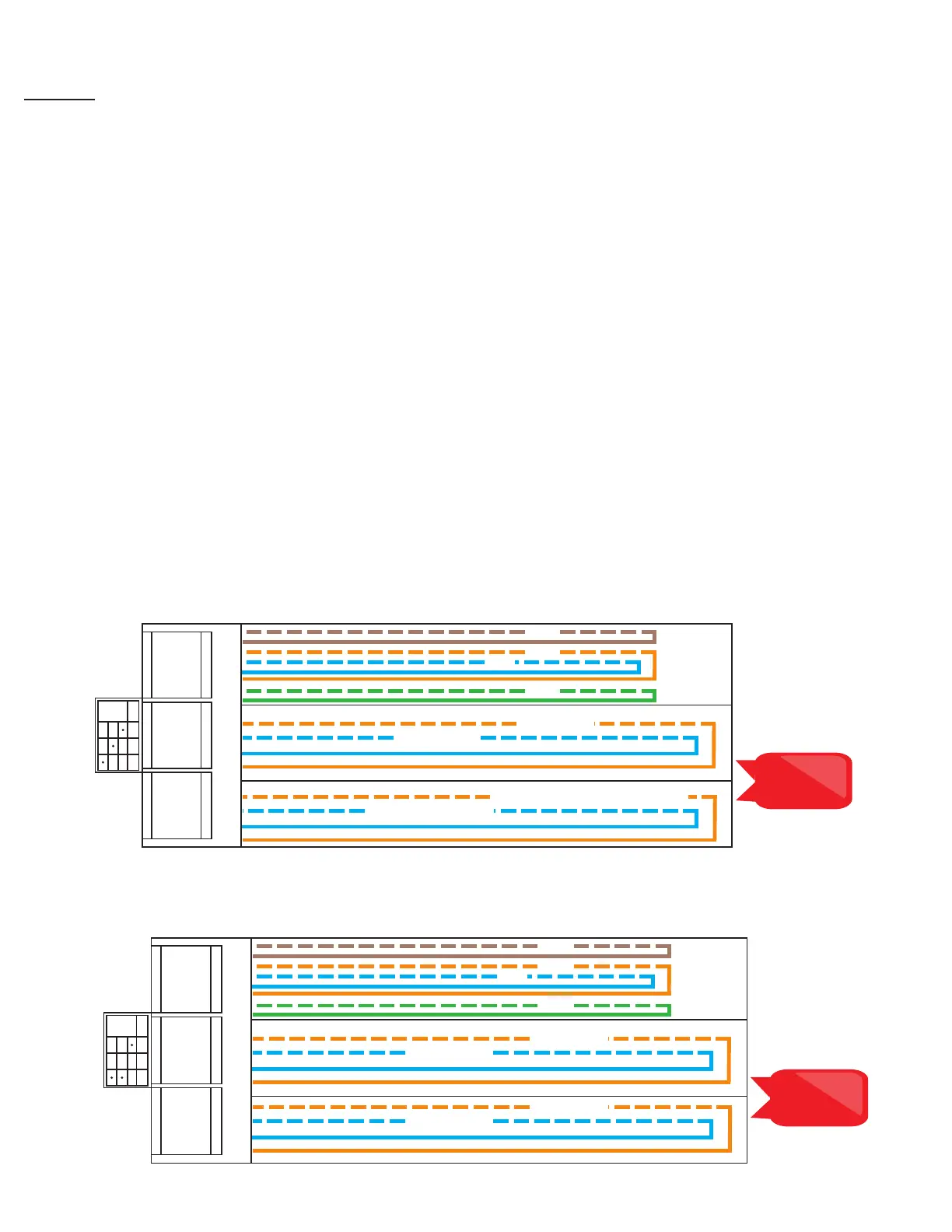
• Plug the supplied RJ45 pigtail cables into the RJ45 interface connections following the wiring chart and pin
out color scheme below.
• Refer to the top of the cards to see what type of RJ45 interface and number of extensions
• The same pin-out color scheme should be used for the primary card and for all additional cards. The
system uses T568-A for pin-out wiring.
• Each card installed in 5-16 line units will have 3 RJ45 interface connections
• The rst card installed will always be:
• Interface 1 (01-04): connection for up to 4 phones (SLT)
• Interface 2 (05-06): connection for up to 2 Telco lines (TWT)
• Interface 3 (07-08): connection for up to 2 Command Center Phones (DKP)
• Each additional card is used for connecting phones and phone lines:
• Interface 1 (01-04): connection for up to 4 phones (SLT)
• Interface 2 (05-06): connection for up to 2 Telco lines (TWT)
• Interface 3 (07-08): connection for up to 2 Telco lines (TWT)
Card 1 Example
Card 2 Example
S01-S04
S05-S06 S07-S08
2003
2004
COMMAND CENTER 1
SLT TWT DKP
01 - 04
05 - 06
07 - 08
SECONDARY COMMAND CENTER
TELCO LINE 1
TELCO LINE 2
2001
2002
PHONE 1
PHONE 2
PHONE 3
PHONE 4
Note: Do not use
the green and
brown pairs
S01-S04
S05-S06 S07-S08
2007
2008
pg. 6
TELCO LINE 5
SLT DKP TWT
01 - 04
05 - 06
07 - 08
TELCO LINE 6
TELCO LINE 3
TELCO LINE 4
2005
2006
PHONE 5
PHONE 6
PHONE 7
PHONE 8
Note: Do not use
the green and
brown pairs