Do you have a question about the Rational SelfCookingCenter SCC and is the answer not in the manual?
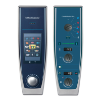
Details on accessing and navigating manual cooking modes via the operator panel.
Refers to Intelligent Level Control processes available on the operator panel.
The main rotary dial used for navigation and selection on the operator panel.
Icons representing different ICC cooking processes like Poultry, Fish, etc.
Access to user-saved favorites, system settings, and administration.
User interface view showing cooking steps and progress in demo mode.
Displays additional intelligent level control information, like time adjustments.
Shows iLC Messenger details and post-cooking tasks for process transparency.
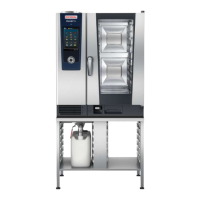
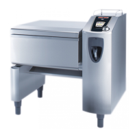
Identifies key components within the SCC unit via diagrams and labels.
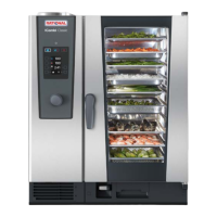
Identifies key components within the SCC_XS unit via diagrams and labels.
Controls for Steam, Hot Air, Combination, and Finishing modes.
Controls for temperature, time, core probe, and preheating settings.
Functions for uploading/downloading programs and data via USB.
Functions for descaling, emptying steam generator, and unit settings.
Details on available CleanJet programs (CLE1, CLE2, CLE3).
Procedure for descaling the steam generator using the CALC function.
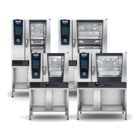
Details on CM_P Index I, CleanJet, door, hand shower, and XS models.
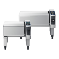
Identifies key components within the CM_P unit via diagrams and labels.
How to check water level in diagnostic mode using level electrode S2.
Explains the automatic water changing process and its triggers.
Explains how scale affects the steam generator and CDS sensor.
Details how the CDS sensor monitors water flow and scale build-up.
The unit performs an automatic self-test after installation for calibration.
Explains the importance and process of humidity calibration for cooking.
Conditions required before starting manual humidity calibration.
Steps for performing manual humidity calibration after specific service work.
Explains the meaning of various error codes and their corresponding problems.
Guides on checking specific components for errors.
Steam control using thermocouple B1 below boiling point.
Steam control using differential pressure sensor P1 above boiling point.
Explains how the Clima valve (Y5) regulates humidity.
Steps for running a manual cooking mode.
Schematic of the main CPU board (A1) and its connectors.
Schematic of the main PCB (A2) and its connector layout.
Lists terminal connections and functions for Interface PCB A1.
Lists terminal connections and functions for Main PCB A2.
Explains status LEDs V68 and V10 for CPU and power supply.
Rules for using the SD card, including data integrity and transfer.
Describes actions for replacing PCBs with/without SD cards.
Step-by-step flowchart for replacing a defective SCC PCB.
Importance of updating software after PCB replacement.
Identifies components and their connections on the CM_P PCB.
Details power supply connections and fuse ratings for the CM_P PCB.
Step-by-step guide for replacing a CM_P PCB and initial setup.
Procedures for addressing errors like E17 and EEPROM issues after PCB change.
Information on using the correct USB stick and software version.
Step-by-step guide for updating software on SCC and CM_P units.
How to download diagnostic, info, and HACCP data to a USB stick.
Information on the unit's battery and when it needs replacement.
Details on startup reports, software versions, and basic settings.
Displays real-time sensor, Clima, and water/motor status data.
Logs for service events and component running times.
Explains the format and fields of HACCP data logs.
Defines additional indicators and process termination statuses in HACCP data.
Guide on when to perform Self Test, Calibration, Update etc. for SCC/CM_P.
Guide on when to perform actions after PCB change, SD recovery, or during maintenance.
Details on fan motor rotation, speeds, and specifications for different unit sizes.
Information on common fan motor failures and related error messages.
Describes the specific fan motor used in SCC_XS 60 units.
Information on separating the motor and inverter for servicing.
Diagram and explanation of bus connection for electric units.
Diagram and explanation of bus connection for gas units.
Explains error messages related to bus communication failures.
Information on LED lights in SCC units and CM_P XS.
Details the different PCB A7 types used for LED lighting and level indication.
Diagram showing the internal structure of a Solid State Relay.
Procedure for testing SSR operation for hot air and steam elements.
Procedure to check heating elements using SSRs at 100% power.
Wiring diagram for SSR control of heating elements.
Procedure to check heating elements using SSRs at 100% power for 3AC units.
Wiring diagram for SSR control of heating elements in 3AC units.
How cooling fans are controlled and their role in unit cooling.
Guidance on cleaning or replacing the air filter for cooling fans.
Explains the open and closed positions of the drain valve.
How to perform a function test on the drain valve and check its micro switch.
Interpreting the maintenance status and cleanliness indicators.
Details on available Cleanjet programs, chemicals, and usage.
Table of error codes, problems, and reset procedures for CleanJet+Care.
Procedure for handling interruptions during a CleanJet program.
Available Cleanjet programs (CLE1, CLE2, CLE3) for CM_P units.
How the scale detection system works and its configuration.
Overview of features like remote control, status display, and data upload.
Steps for setting up and registering the unit for ConnectedCooking.
Steps to enter the service menu, including password and available options.
Overview of service functions like Diagnostic, Basic Settings, Function Test, Calibration.
Displays real-time temperature and status of various sensors.
Real-time data for Clima system status, RPM, and motors.
Real-time status of solenoids, pumps, valves, and motors.
Displays accumulated running times for components like pumps, valves, and fans.
Shows total running hours for different cooking modes and heating.
Table listing service errors, definitions, and corresponding reasons/remedies.
Detailed explanations for specific errors like Service 10, 20, 25, 26, 27, 28, 29.
Table listing service errors, definitions, and corresponding reasons/remedies.
Detailed explanations for specific errors like Service 30, 31, 34, 35, 36, 37, 40, 41, 42, 44.
Table listing service errors, definitions, and corresponding reasons/remedies.
Interpretation of motor blink codes for SCC_CMP units.
Groups gas errors into ignition box failures and electrode/burner issues.
Lists gas error numbers and recommended actions for CM_P.
Settings for water supply, drain valve, steam corrosion, and cleaning control.
Settings for UltraVent activation, gas type, and blower speed calibration.
Tests for heating elements, motors, and fan speeds.
Tests for valves, pumps, LEDs, speakers, and other components.
Conditions required before performing manual humidity calibration on SCC.
Step-by-step guide for manual humidity calibration, including error causes.
Steps to enter the CM_P service menu using DIP switches.
Overview of CM_P service functions like Diagnostic, Error History, Basic Settings.
Diagnostic displays for software version, sensors, and core probe.
Diagnostic displays for Clima system, fan motors, and voltage signals.
Table of error messages, descriptions, and remedies for CM_P.
Details on errors like E2, E10, E17, E20, E26, E28, E29, E30, E31.
Table of error messages, descriptions, and remedies for CM_P.
Interpretation of fan motor blink codes for CM_P units.
Groups gas errors into ignition box failures and electrode/burner issues.
Lists gas error numbers and recommended actions for CM_P.
Displays accumulated running times for CM_P components.
Shows total running hours for CM_P cooking modes.
Settings for SC Automatic, SC pump, gas type, and CO2 screw length.
Settings for steam heating, quenching temperatures, and show mode.
Tests for heating elements, motors, and fan speeds in CM_P.
Tests for valves, pumps, LEDs, speakers, and other components in CM_P.
Conditions required before performing manual humidity calibration on CM_P.
When manual calibration is needed after specific service work.
| Model | SelfCookingCenter SCC |
|---|---|
| Temperature Range | 30°C to 300°C |
| SelfCookingControl | Yes |
| HiDensityControl | Yes |
| iLevelControl | Yes |
| Material | Stainless steel |
| Capacity | Varies by model |
| Dimensions (W x D x H) | Varies by model |
| Weight | Varies by model |
| Cleaning System | Automatic cleaning |
| Steam generator output (SCC 201) | 18 kW |