5
P/N 016-5032-114 Rev. A 37
CAB COMPONENT INSTALLATION
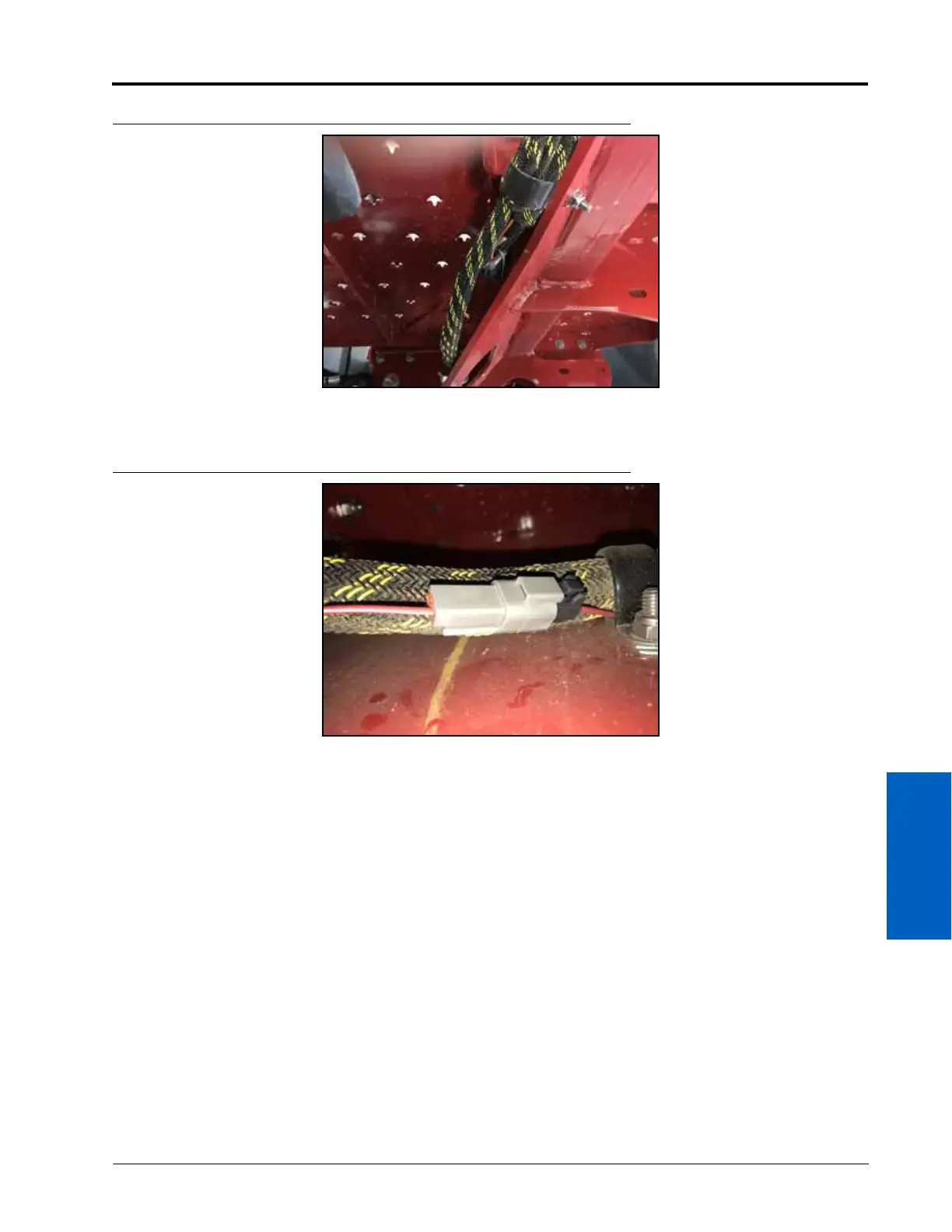
FIGURE 22. Steering Lockout Cable Routing
4. Route the remaining connector to the left-rear tire of the machine.
FIGURE 23. Steering Lockout Cable Connection
5. Connect the TO MACHINE’S FOUR WHEEL STEER (FW355) CONNECTOR to the machine’s FW355 connection.

 Loading...