APPENDIX A
10 Raven Switch Pro™ Installation & Reference Manual
SWITCH PRO COMBO CABLE CONNECTIONS
1. Connect the main and auxiliary interface connectors (conduit with a pair of connectors) to the back of the
Envizio Pro or Viper Pro field computer.
2. Connect the large round 37-pin connector (conduit with speed input terminals) to the back of the Switch Pro.
3. Connect the existing SCS console cable to the combo cable included with the kit:
a. For kits with combo cable (P/N 115-0171-820) connecting to SCS 440/450 cabling, connect the 16-pin
connectors on the existing console cable and combo cable. If the speed and pressure sensors will be
used, reconnect the existing sensor cables to the Speed (14-pin) and pressure (3-pin) connectors on the
combo cable.
b. For kits with combo cable (P/N 115-0171-821) to SCS 4400 cabling, connect the 37-pin connectors on the
existing console cable and combo cable.
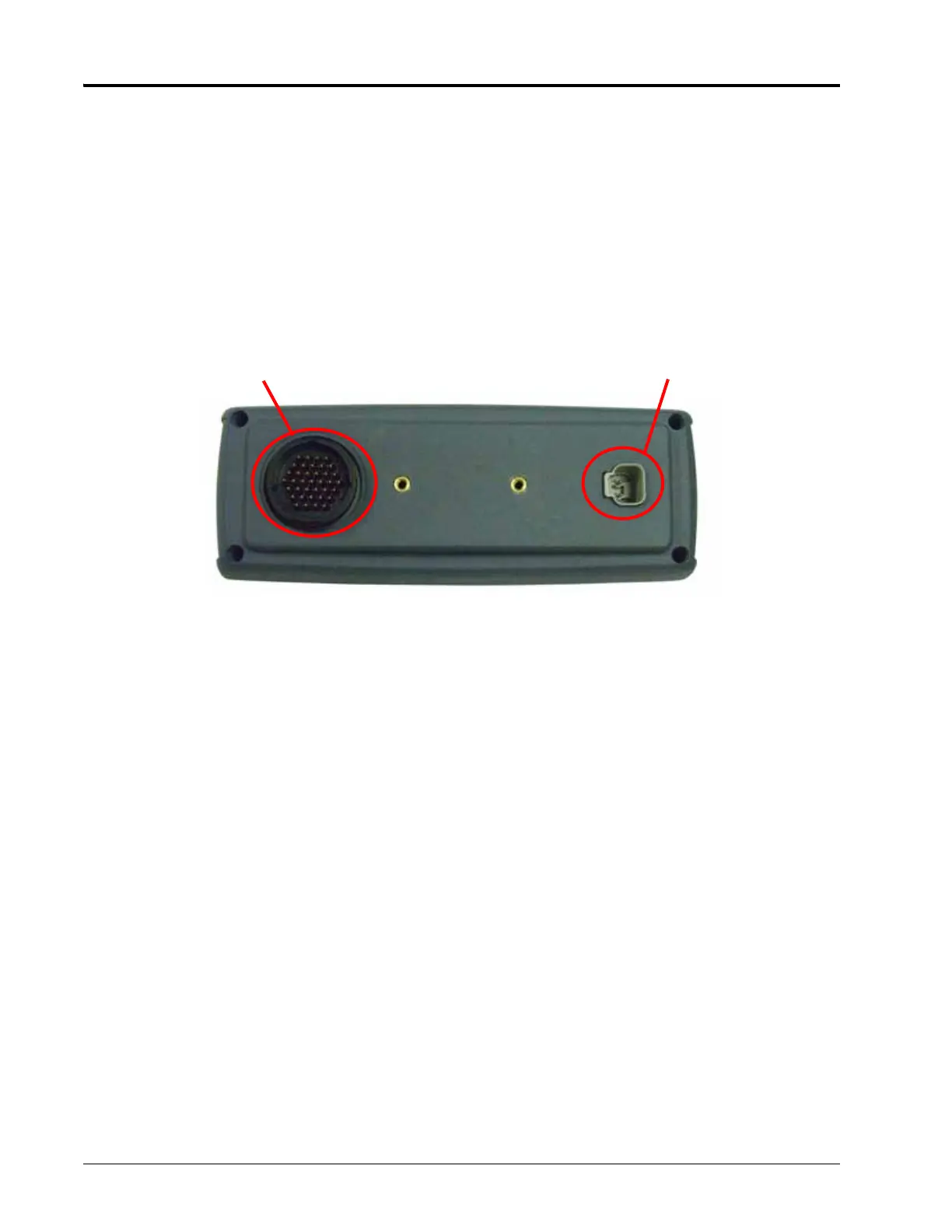
4. Insert the Switch Pro logic power connector to the power port on the back of the Switch Pro unit.
5. Install the supplied CAN passive terminators as shown in Appendix B, System Diagrams, for the Switch Pro
system. Use the appropriate diagram to verify hook-up.
Switch Pro Cable Port Logic Power Port