S
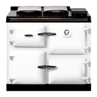
SEE FIG. 5
To remove blast tube, slacken two grub screws, pull
forward.
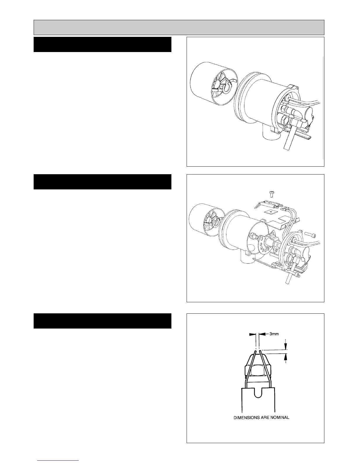
SEE FIG. 6
1. Remove two socket head screws.
2. Remove head assembly complete.
3. Disconnect ignition leads.
4. Remove ignitor assembly, by removing countersunk
screw and clamp.
5. Unscrew nozzle from its holder with a correctly fitting
tubular spanner to avoid damage to hexagon.
SEE FIG. 7
1. Replace nozzle with a new one of the same make and
specification, 0.35 @ 80°S.
2. Ensure that mating faces are clean.
3. Hold nozzle holder with correct spanner when
tightening nozzle.
4. Typically finger tight plus 1/4 turn with spanner is
sufficient.
DO NOT OVERTIGHTEN.
5. Ensure electrode gaps are correct.
8
INTRODUCTION
Burner Servicing
Fig. 5 DESN 515765
COOKER BURNER
Fig. 6 DESN 515766
BURNER NOZZLE REMOVAL
Fig. 7 DESN 510538
3mm
BURNER NOZZLE REPLACEMENT
 Loading...