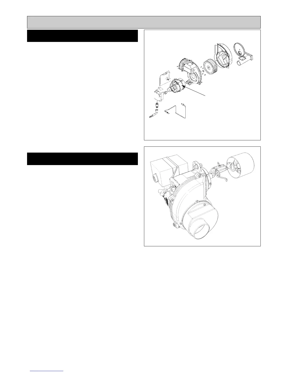
SEE FIG. 22
Follow instructions in sections BURNER ACCESS, Steps
1 to 3 and BURNER REMOVAL.
1. Isolate electric supply.
2. Remove 3-pin plug.
3. Remove solenoid plug.
4. Disconnect oil pipe.
5. Undo 2 screws and remove snorkel.
6. Remove 4 countersunk screws from fan case and split
the case.
7. Remove grub screw and withdraw fan.
8. Remove 4 countersunk screws and remove fan motor
from case.
9. Remove 3 socket head screws and withdraw pump.
10.Re-assemble in reverse order.
NOTE: Ensure that gaskets and seals are in place and in
good condition.
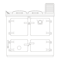
SEE FIG. 23
1. Release two countersunk head screws and remove
blast tube.
2. Remove two screws and slide out nozzle support
cradle c/w ignitor assembly from burner head.
3. Disconnect ignition leads.
4. Remove ignitor assembly by removing countersunk
screw and clamp.
5. Fit new ignition electrode assembly, re-assemble in
reverse order.
6. Check electrode gap and reset if necessary.
17
FAN MOTOR
Fig. 22 DESN 515970
IGNITION ELECTRODES
Replacement of parts (Burner)
Fig. 23
FAN MOTOR