Installation
Important: This thermostat must be installed according to all national
and local electrical codes. The installation must be performed by quali-
fied personnel.
Locating the floor temperature sensor
The floor temperature sensor is installed under the floor surface. See
the QuickNet System Installation Manual (H57704), Section 6, for more
details.
Ifrequired,thesensorcablecanbeextendedtoabout300ft(91m).
Wiring the thermostat
WARNING:TURNOFFTHEPOWERTOTHECIRCUITATTHEMAIN
POWERPANELTOAVOIDELECTRICSHOCK.
WARNING:SHOCKHAZARD.TOPREVENTSHOCK,THEQUICKNET
FLOORHEATINGMATMUSTBECONNECTEDTOGROUND.
WARNING:SHOCKHAZARD.THISDEVICEDOESNOTPROTECT
AGAINSTELECTROCUTIONWHENPOWEREDAT208VOR240V.A
SEPARATEGROUNDFAULTCIRCUITINTERRUPTER(GFCICLASS
A) MUST BE USED.
WARNING:ENSURETHATTHELINEWIRESARECONNECTED
TOTHEPROPERTERMINALS.FAILURETODOSOCOULDCAUSE
SERIOUSBODILYINJURYORDEATH.
1. Connect power to the thermostat’s line terminals marked “L1 (L)”
and “L2 (N)”. For 120-V installations, be sure the neutral wire is
connected to “L2 (N)”.
2. Connect the floor heating cold lead to the load terminals marked
“Load 15 A Max”.
3. Connect the floor heating cold lead braid (ground) to the supply
ground in the electrical junction box.
4. Connect the floor temperature
sensor to the screw-less
terminals marked “Sensor”.
Push on the terminal spring
with a screwdriver and
insert the wires.
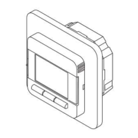
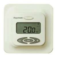
Mounting the thermostat in the electrical box
1. Use a screwdriver to remove the cover.
2. Mount the thermostat in the wall socket and re-attached the cover.
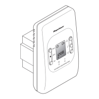
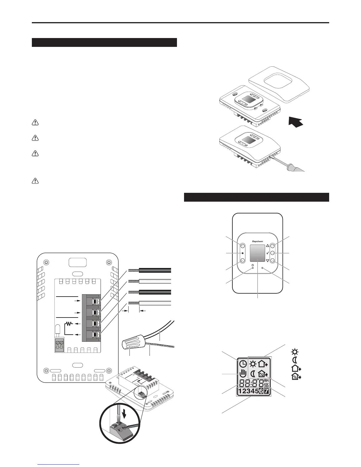
Thermostat Controls and Display Symbols
The following figure shows the thermostat controls:
Reset
GFCI
Test
R
Reset button
Red light indicating
ground-fault
Test button
Pin button for
adjusting clock
Adjustment up
OK - accept
Digital
display
Adjustment down
Reset button for
factory settings
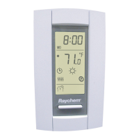
The following figure shows the symbols that appear in the display
window while you are programming:
L1 (L)
L2 (N)
240/(120)VAC
15 A
Max.
QuickStat
®
GFCI Class A
LINE
LOAD
SENSOR
1/4" (6 mm)
Strip length
Line (black)
Line 2 (red) or Neutral (white)
Cold lead
Cold lead
QuickStat Installation & Operation Manual
2
Supply
ground
Cold lead
ground
Wire nut
Clock function
Manual mode
Time and
temperature
Day number
4-event symbol:
Wake
Night
Out
Home
% switch-on time
Heating on
L1 (L)
L2 (N)
240/(120)VAC
16A
Max.
QuickStat
®
GFCI Class
A
LINE
LOAD
SENSOR
CAUTION:
High Voltage - Disconnect
power supply before servicing
DUAL VOLTAGE 50/60 Hz
3840W/240VAC (16A)
1920W/2120VAC (16A)
 Loading...