Wuhan Raycus Fiber Laser Technologies Co., Ltd.
User Guide of RFL-C100~RFL-C2000S
37
PIN 7-9 of the DB25 control interface is applied to 24V (enable hardware
emission);
Send the start or stop emitting command (enable hardware emission) to control the
emission by the PC software;
9) The laser is controlled by the user's "modulation" signal provided by the external MOD
interface
See 4.8 to get the process of laser shutting down.
4.7.4 AD mode
When PIN 7-9 of the DB25 control interface is applied to 24V, the laser enters the external
AD mode, and the power of the laser is controlled by the voltage obtained by PIN 22-25 of the
DB25 interface connector (1V-10% power, 10V-100% power).
When PIN 7-9 of the DB25 control interface is applied to 0V or left floating, the power of
the laser is set by serial port or Ethernet.
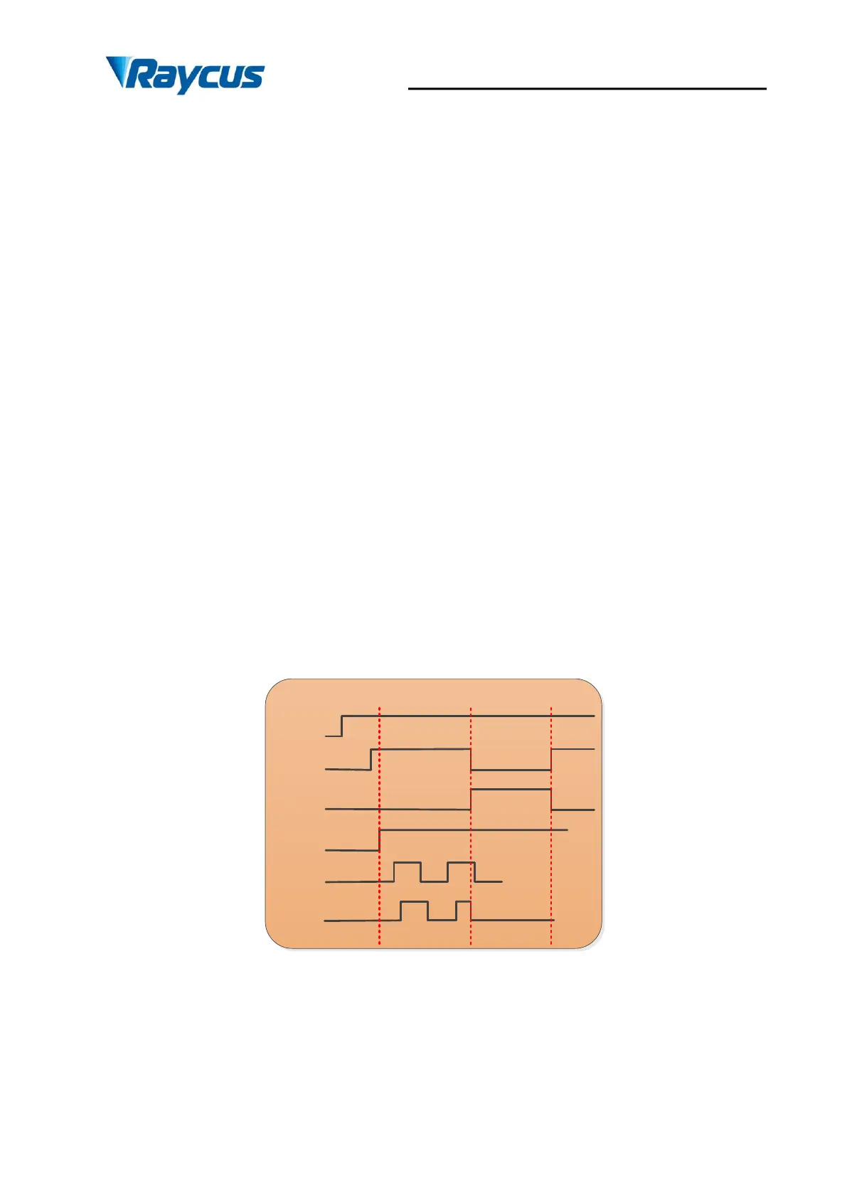
4.7.5 Control sequence diagram
CW Mode——duty=100%
power
ready
ALARM
Laser
on/off
EMON/
EMOFF
laser
>10s
>1ms
>1ms
<20us <20us
Figure 27 Control sequence diagram of CW mode