PART I. User & Installation Manual
36 1417WCE
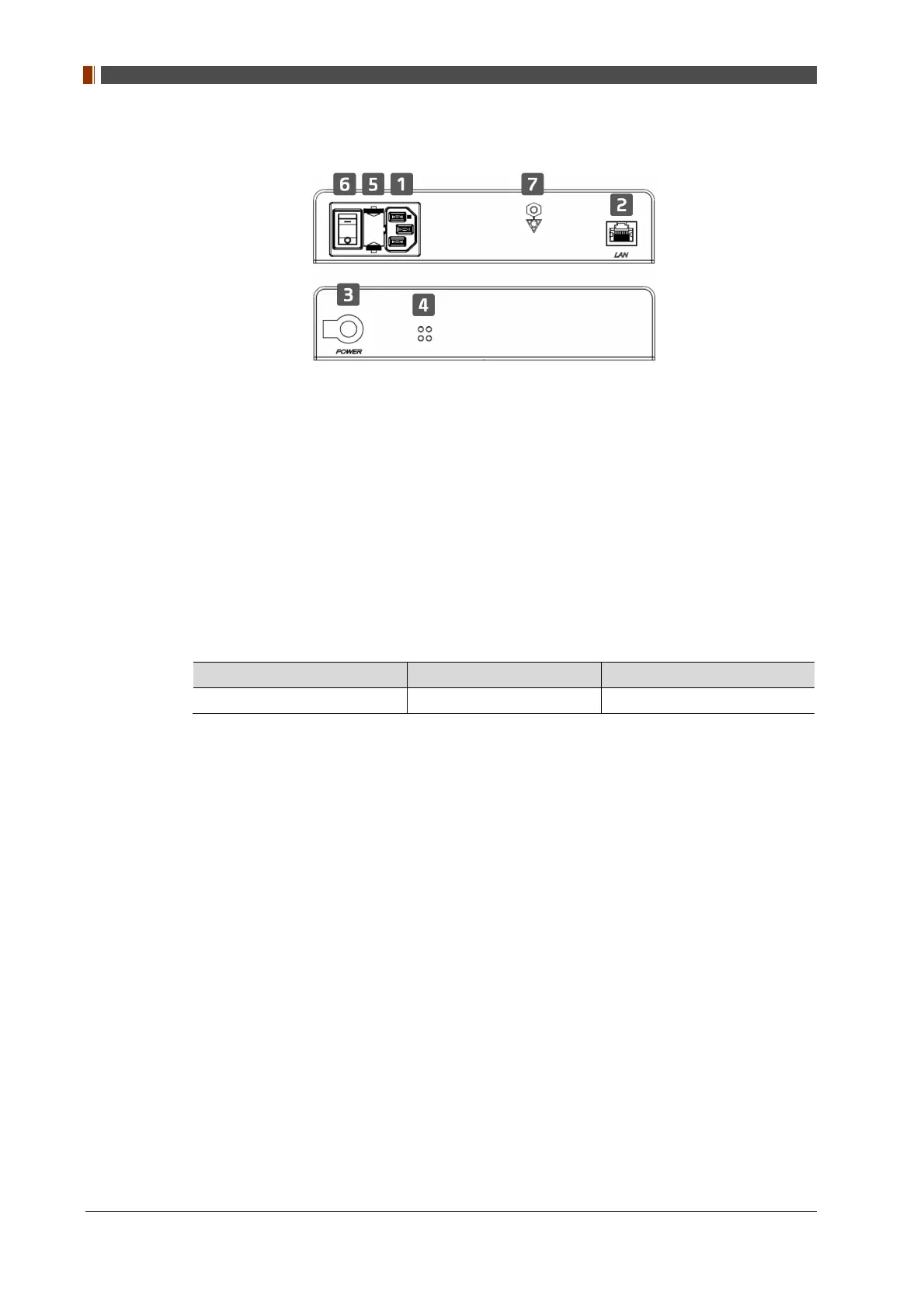
2.3.3 Power Suppy (Optional)
1. Power Plug Connector
Connects to the AC power cord
2. LAN Connector
Ethernet port for transmitting an image/command between the detector and PC
3. Link Connector
Used for charging the battery while the detector is in use (Connect the detector and power
supply)
4. LED Indicator
Display status of the power supply.
Color Status Power Status
Green On Power on
5. Fuse
T3.15 AH 250V
6. Switch
Power On/Off switch
7. Frame ground
 Loading...