1.Carefullyliftoneedgeofthescreenprotection
lm,sothatitisaccessibleforremovingwhenunit
installationiscomplete.
2.Ensurethememorycardslotdoorisintheopen
position.
3.Orientatethebottom-rightsideofthebezelunderthe
lipofthechartcarddoorandplacethebezelover
thefrontofthedisplay,ensuringthattheclipsalong
thebottomedgeofthebezellatchintoposition.
4.Ensurethebezeliscorrectlyalignedwiththedisplay,
asshown.
5.Applyrmbutevenpressuretothebezelalongthe:
i.Outeredges-workfromthesidesupwardsand
thenalongthetopedge,toensurethatitclips
securelyintoposition.
ii.Inneredges-particularlyalongthechartcard
dooredge,toensurethatthebezelsitsat.
6.CheckthatthePowerbuttonandchartcarddoor
arefreetooperate.
Removingthefrontbezel
Beforeproceedingensurethememorycardslotdoor
isopen.
Important:Usecarewhenremovingthebezel.Do
notuseanytoolstoleverthebezel;doingsomay
causedamage.
1.Placebothyourthumbsontheupperleftedgeof
thedisplay,atthepositionsindicatedinthediagram
above.
2.Placeyourngersunderneaththebezel,atthe
positionsindicatedinthediagramabove.
3.Inasinglermmotion,applypressuretotheouter
edgeofthedisplaywithyourthumbsandpullthe
bezeltowardsyouusingyourngers.
Thebezelshouldnowcomeawayfromthedisplay
easily.
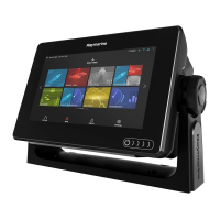
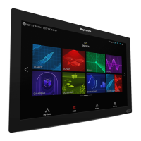
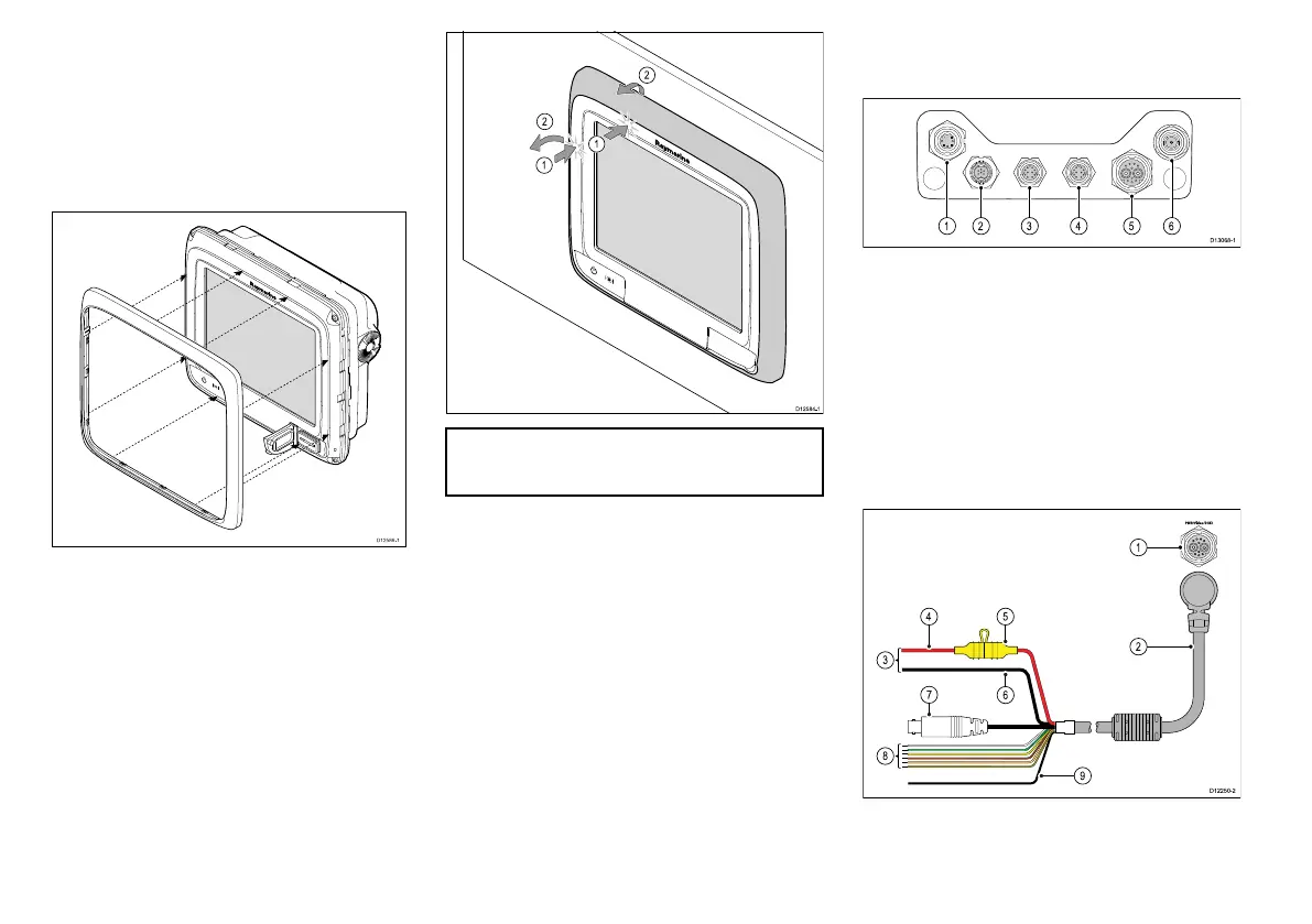
a9xanda12xconnectionsoverview
Thea9xanda12xvariantMFDsincludethefollowing
connections.
1.Sonartransducer(a97anda127)/DownVision
TM
transducer(a98anda128)
2.SeaTalk
ng
3.Network1(RayNet)
4.Network2(RayNet)
5.Poweranddata
6.GA150antenna
Poweranddataconnection
ThedetailsbelowapplytoMFDswhichhavea
combinedpoweranddatacable.
1.Poweranddataconnection
2.Poweranddatacable
10a9x/a12x
 Loading...