Do you have a question about the Raymarine a9 Series and is the answer not in the manual?
Product must be installed and operated per instructions to avoid injury, damage, or poor performance.
Product is not approved for hazardous/flammable atmospheres. Do NOT install in such areas.
Product contains high voltages. Do NOT remove covers or access internal components.
Ensure product is correctly grounded before applying power, per guide instructions.
Ensure vessel's power is OFF before installation. Do NOT connect/disconnect with power ON.
Ensure all personnel are clear before rotating the radar scanner.
Ensure personnel are clear of the scanner during radar transmission.
Never operate sonar with vessel out of water or touch transducer when powered.
Ensure power source is adequately protected by a suitably-rated fuse or circuit breaker.
Ensure units are adequately supported on a secure surface. Do NOT mount or cut holes that damage vessel structure.
Mount unit to allow proper cable routing. Minimum bend radius of 100mm required. Use cable supports.
Select a location far from interference sources like motors, generators, and radio transmitters.
Consider environmental factors for internal GPS antenna placement. Above decks is optimal.
Above decks offers optimal GPS performance. Below decks may require an external antenna.
Maintain adequate distance from magnetic compasses to prevent interference. Keep display away from compasses.
Select location, identify cable routes, detach front bezel before mounting.
Prepare mounting surface, apply gasket, connect cables, and secure unit using provided fixings.
Recommend connecting all power via distribution panel with breaker/switch and circuit protection.
Connect dedicated shield (drain) wire to RF ground point or battery negative.
Do not connect unit to a system with positive grounding.
Guidance on protecting product with breakers/fuses. Example arrangements provided. Consult dealer if unsure.
Recommended wiring via distribution panel with thermal breaker/fuse. Lists connection points.
Wiring directly to battery if no distribution panel/RF ground. Connect drain wire to negative terminal.
Wiring directly to battery if no distribution panel. Connect drain wire to RF ground point.
Connect NMEA 0183 devices using power/data cable for MFDs. Note a6x/a7x requires adapter.
Details MFD ports for NMEA 0183 devices (input/output, baud rates).
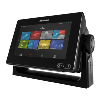
Provides 2D/3D graphical view for navigation, waypoint, route, and track functions.
Helps distinguish fish, bottom structure using transducer/sonar. View depth/temp, mark points.
Tracks targets, measures distances/bearings using radar scanner. Auto gain and color modes included.
Alerts to situations/hazards. Configured via message dialog or Alarms menu.
| Touchscreen | Yes |
|---|---|
| Power Supply | 12V DC |
| Resolution | 800 x 480 |
| Display Type | LCD |
| Waterproof Rating | IPX6 |
| GPS | Built-in |
| Networking | NMEA 2000, Wi-Fi |
| Video Input | Yes |
| Cartography | Navionics, C-MAP |
| Display Size | 9 inches |