Do you have a question about the Raymarine E70098 and is the answer not in the manual?
Crucial safety and operational warnings for system installation and use.
Details product compliance, disposal, and warranty information.
Outlines the purpose and scope of the installation handbook.
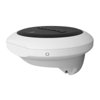
Describes the Evolution autopilot system components and features.
Lists essential, recommended, and optional components to complete the system.
Lists compatible Raymarine autopilot control units for the system.
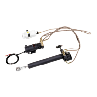
Details compatible drive units based on vessel type and ACU.
Lists components included with the EV-1 and EV-2 sensor units.
Lists components included with the ACU-100 and ACU-150 units.
Provides physical dimensions for the EV-1 and EV-2 sensor units.
Provides physical dimensions for the ACU-100 and ACU-150 units.
Outlines the key steps for installing the autopilot system.
Important safety and installation warnings to consider before proceeding.
Specifies suitable mounting locations and orientation for the EV-1/EV-2 sensor.
Specifies suitable mounting locations for the ACU units.
Guidance on maintaining adequate distance from magnetic compasses for interference prevention.
Detailed instructions for mounting and installing the EV-1 sensor unit.
Instructions for mounting and connecting the ACU units (ACU-100/150 and ACU-200/300/400).
Refers to dedicated documentation for installing various autopilot drive units.
Best practices for cable routing, strain relief, and shielding.
Identifies the connection ports on the EV-1 and EV-2 units.
Details how to provide power to the EV-1 unit via the SeaTalkng backbone.
Comprehensive guide to connecting the ACU-100 and ACU-150 units.
Explains the power supply requirements and circuit protection for ACU-100/150.
Explains the importance and connection of the rudder angle sensor.
Covers the connections for ACU-200, ACU-300, and ACU-400 units.
Details power supply and circuit protection for ACU-200/300/400.
Describes connecting legacy SeaTalk pilot controllers via a converter.
Essential checks to perform after installation before commissioning.
Guidance on initial setup and commissioning of the autopilot system.
Lists system alarms, possible causes, and recommended solutions.
Interprets LED status codes on the EV-1 unit for diagnostics.
Refers to documentation for operating the autopilot system with various controllers.
Recommended regular checks for reliable equipment operation.
Guidelines for safely cleaning the autopilot system components.
Provides contact information and resources for product support and service.
Lists resources like videos and training for learning about products.
Detailed technical specifications for the EV-1 and EV-2 sensor units.
Detailed technical specifications for the ACU-100 and ACU-150 units.
Lists available spare parts and their part numbers.
Lists various SeaTalkng cables and accessories for system expansion.
| MPN | E70098 |
|---|---|
| Type | Autopilot System |
| Seatalk NG Compatible | Yes |
| Power Supply | 12V DC |
| Communication Protocol | SeaTalkng, NMEA2000 |
| GPS Receiver | No |
| In The Box | EV-1 Sensor Core |
| Operating Voltage | 12 V DC |
| Drive Unit Type | Mechanical or hydraulic |
| Compatibility | Raymarine MFDs, NMEA 2000 devices |
| Dimensions | Varies by component |
| Weight | Varies by component |