Do you have a question about the Raymarine E70096 and is the answer not in the manual?
General safety warnings and cautions for installation and operation.
Disclaimers, product compliance, and connection guidelines.
Product disposal instructions and warranty registration information.
Usage scope, regulations, and technical document accuracy.
Details about the handbook, applicable products, and related documentation.
Guidance on document illustrations and text conventions used.
Description of the Evolution autopilot system components and features.
Lists essential, recommended, and optional components for system completion.
Explanation of the SeaTalkng ® networking protocol.
Raymarine scheme for managing multiple data sources on a network.
Illustrative diagrams of typical Evolution autopilot system configurations.
Lists compatible autopilot controllers for the Evolution system.
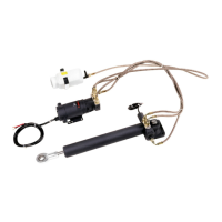
Details on compatible drive units based on drive category and ACU.
Information on how to update product software for performance improvements.
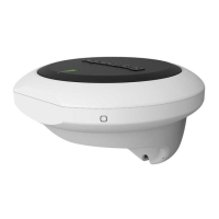
List of parts included with the EV-1 and EV-2 sensor.
List of parts included with the ACU-100 and ACU-150.
List of parts included with the ACU-200, ACU-300, and ACU-400.
Physical dimensions of the EV-1 and EV-2 sensor unit.
Physical dimensions of the ACU-100 and ACU-150 units.
Physical dimensions of the ACU-200, ACU-300, and ACU-400 units.
A checklist of activities required for system installation.
Important warnings and cautions related to component placement.
Guidance on avoiding installation near potential ignition sources.
Specific location requirements for mounting the EV-1 and EV-2 sensor.
Specific location requirements for mounting the ACU units.
Guidelines for maintaining safe distances from magnetic compasses.
Recommendations for ensuring optimal Electromagnetic Compatibility (EMC) performance.
Instructions for installing the EV-1 Attitude Heading Reference Sensor.
Instructions for mounting and connecting the ACU-100 and ACU-150.
Instructions for mounting and connecting the ACU-200, ACU-300, and ACU-400.
References to dedicated installation instructions for various autopilot drive units.
Best practices for cable type, length, routing, strain relief, and shielding.
Diagram showing connection ports on the EV-1 and EV-2 units.
Procedure for connecting SeaTalkng ® cables to the sensor unit.
Information on powering the EV-1 unit via the SeaTalkng ® backbone.
Understanding Load Equivalency Number (LEN) for SeaTalkng ® system configuration.
Recommendations for powering the SeaTalkng ® backbone.
Diagram showing connection points on the ACU-100 and ACU-150.
Diagram illustrating a typical recommended system setup for ACU-100/150.
Details on power connection, colors, fuses, and circuit protection.
Instructions for proper grounding of the ACU units.
Electrical considerations for power and drive cable runs and sizing.
Table for selecting appropriate cable size based on drive type, voltage, and length.
Instructions for connecting the drive motor to the ACU-100/150.
Procedure for connecting the ACU to the SeaTalkng ® backbone.
Importance and procedure for connecting a rudder angle sensor to the ACU.
Diagram of connection ports on the ACU-200.
Diagram of connection ports on the ACU-300.
Diagram of connection ports on the ACU-400.
References to sections for connecting system components to the ACU.
Diagram illustrating a typical recommended system setup for ACU-200/300/400.
Details on power connection, fuses, and circuit protection for ACU-200/300/400.
Instructions for proper grounding of the ACU units.
Instructions for connecting drive motor and clutch to ACU-200/400.
Information on clutch power output and its impact on the SeaTalkng ® backbone.
Ensuring correct clutch voltage switch setting on the ACU.
Instructions for connecting solenoid and bypass valves to the ACU-300.
Procedure for connecting the ACU-400 to ZF-Marine VMU using an adapter.
Procedure for connecting ACU-200/300/400 to the SeaTalkng ® backbone.
Operation of the SeaTalkng ® power switch on the ACU for backbone power.
Connecting a sleep switch to disable autopilot operation.
Importance and procedure for connecting rudder angle sensor to ACU-100/150.
Connecting legacy SeaTalk pilot controllers via a converter.
Checks to perform after installation and before system commissioning.
Essential steps for proper autopilot system commissioning.
Adjusting rudder damping for optimal autopilot performance.
Explanation of autopilot system alarms, possible causes, and solutions.
Interpreting LED status indicators on the EV-1 unit.
Interpreting LED status indicators on the ACU units.
Guidance on operating the autopilot system via control units or MFDs.
Information on product service, maintenance, and authorized repair.
Recommended routine checks for ensuring reliable equipment operation.
Best practices for cleaning the autopilot system components.
Information on accessing Raymarine's support, warranty, and repair services.
Resources for learning more about Raymarine products, including videos and training.
Detailed technical specifications for the EV-1 and EV-2 sensor units.
Detailed technical specifications for the ACU-100 and ACU-150 units.
Detailed technical specifications for the ACU-200, ACU-300, and ACU-400 units.
List of available spare parts and their part numbers.
Information about the Evolution SeaTalkng ® cable kit and its contents.
Catalog of SeaTalkng ® cables and accessories for system expansion.
| Brand | Raymarine |
|---|---|
| Model | E70096 |
| Category | Autopilot System |
| Language | English |