Do you have a question about the Raymarine GA200 and is the answer not in the manual?
Ensure vessel's power is switched OFF before starting installation. Do NOT connect/disconnect with power on.
Product not approved for hazardous/flammable atmospheres. Do NOT install in such areas.
Declaration that GA200 Antenna complies with Radio Equipment Directive 2014/53/EU.
Guidelines for minimizing electromagnetic interference for optimal system performance.
Dispose of product according to WEEE Directive for recycling hazardous materials.
Equipment intended for leisure marine boats and workboats not covered by IMO/SOLAS.
Register product ownership online at www.raymarine.com for full warranty benefits.
Raymarine not liable for errors, product incompatibility, or damages from use.
Information correct at time of printing; check website for latest updates.
Details products for which this document is applicable.
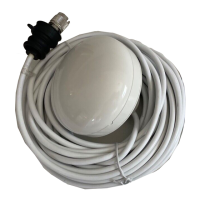
External antenna for improving GNSS reception on compatible MFDs, AIS, and VHF radios.
Lists Raymarine products compatible with the GA200 antenna.
Guidance on selecting an optimal mounting location for clear sky view.
Information on extending the antenna cable length up to a maximum of 20 m.
Maintain a maximum cable bend radius of 50 mm (2 in.) throughout the cable run.
Instructions for mounting the antenna on a suitable pole with a 1 inch 14 TPI thread.
Instructions for mounting the antenna on a flat surface, with options for cable routing.
Steps to connect the antenna cable to a compatible MFD, AIS, or VHF unit.
Common causes and solutions for issues related to no GNSS fix displayed.
Details physical, environmental, and conformance specifications of the GA200 antenna.
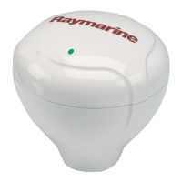
The Raymarine GA200 is an external antenna designed to enhance the reception of internal GNSS (Global Navigation Satellite System) receivers found in compatible Multifunction Displays (MFDs), AIS (Automatic Identification System) devices, and VHF (Very High Frequency) radios. It is important to note that the GA200 is solely an antenna and does not function as a receiver itself; it requires connection to a compatible device that features an internal GNSS receiver.
The primary function of the GA200 antenna is to provide improved satellite signal reception for navigation and positioning systems. It supports multiple satellite systems, including GPS, GLONASS, Beidou, and Galileo. This multi-system compatibility ensures robust and accurate positioning data, which is crucial for marine navigation. For instance, when the Beidou GNSS system becomes available, the GA200 will be essential for receiving its signals, although the connected MFD, AIS device, or VHF radio may also require a software update to enable full support for Beidou.
The antenna is supplied with a 10-meter (33 ft) fitted cable, which can be extended by an additional 10 meters (33 ft) using RG58-Type 50 ohm coaxial cable and reliable, water-ingress-protected connectors, bringing the total maximum cable length to 20 meters (66 ft). Exceeding this recommended maximum length may lead to signal degradation. Throughout the cable run, a maximum bend radius of 50 mm (2 in.) should be maintained to prevent damage and ensure optimal performance.
The GA200 antenna offers flexible mounting options: it can be surface-mounted on a flat horizontal surface or pole-mounted on a standard 1-inch 14 TPI threaded pole.
For pole mounting, the process involves securely attaching the pole mount adaptor to the pole, feeding the antenna cable through the center of the adaptor and pole, and then securing the antenna to the adaptor. It is crucial to ensure the cable is not trapped during this process.
For surface mounting, the cable can be routed either centrally through a drilled hole in the mounting surface (Option A) or from the side of the antenna through a cable channel (Option B). If using Option B, a piece of plastic covering the end of the cable channel must be removed to route the cable. Incorrect cable routing can damage the cable. The antenna is then secured to the surface using supplied mounting studs and thumb nuts.
Connecting the antenna is straightforward: the antenna's cable connector is fully inserted into the corresponding antenna connector on the rear of the MFD, AIS, or VHF unit. For Ray53, Ray63, and Ray73 radios, the GNSS antenna connection is found at the end of a captive cable connected to the radio base unit. A locking collar is then turned clockwise until tight, and a protective boot is pushed over the connection and secured with a cable tie.
Proper placement of the GNSS antenna is critical for optimal performance. It must be mounted in a location that provides a clear, direct line-of-sight to the entire sky, around the horizon. This means avoiding obstructions such as masts, searchlights, or other structures that could block satellite signals. The antenna should be mounted as low as possible to ensure stability, as a more stable antenna more effectively tracks satellites and provides stable data. It should also be placed at least 1 meter (3 ft) away from other antennae and electronic equipment. The antenna should not be mounted in areas where it could be stepped on or tripped over, up a mast (which can cause significant errors due to swinging), in the direct path of a radar beam, or in an engine room.
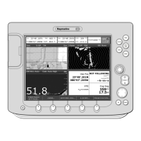
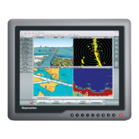
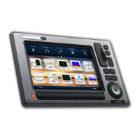
The GA200 is compatible with various Raymarine products, including a Series (a95, a97, a98, a125, a127, a128), eS Series (eS97, eS98, eS127, eS128), Axiom Pro, and Axiom XL MFDs. It also works with AIS receivers such as AIS350, AIS650, AIS700, AIS4000, and AIS5000, as well as VHF radios like Ray53, Ray63, Ray73, Ray90, and Ray91.
The GA200 is designed for low power consumption, contributing to efficient energy use on board. For optimal Electromagnetic Compatibility (EMC) performance, Raymarine equipment and its connected cables should be installed at least 1 meter (3.3 ft) away from any equipment transmitting radio signals (e.g., VHF radios, cables, and antennas), with this distance increased to 2 meters (6.6 ft) for SSB radios. It should also be more than 2 meters (6.6 ft) from the path of a radar beam. The product should ideally be supplied from a separate battery from the engine start battery to prevent erratic behavior and data loss. Using Raymarine specified cables and avoiding cutting or extending them (unless specified in the manual) also contributes to maintaining EMC performance. In areas of extreme EMC interference, separating the product from the interference source by a greater distance can mitigate any slight interference observed.
In case of "no fix displayed" issues, troubleshooting involves checking the geographic location and prevailing conditions, ensuring correct and fault-free GNSS connections and cabling, and verifying that the GNSS receiver has a clear view of the sky. The GNSS (GPS) Status screen, accessible from the display, provides satellite signal strength and other relevant information to aid in diagnosis.
The GA200 is designed to be robust, with IPx6 and IPx7 water ingress protection, ensuring its durability in marine environments. It is also compliant with EN 60945:2002, Radio Equipment Directive 2014/53/EU, and Australia and New Zealand C-Tick compliance level 2.
For warranty benefits, users are encouraged to register their product online at www.raymarine.com. The unit package includes a bar code label with the serial number, which is needed for registration and should be retained for future reference.
| Type | GPS Antenna |
|---|---|
| Frequency | 1575.42 MHz |
| Update Rate | 1 Hz |
| Connector | TNC |
| Cable Length | 10 m |
| Storage Temperature | -40°C to +85°C |
| Humidity | Up to 95% RH |
| Weight | 0.5 lbs |
| Operating Temperature | -25°C to +55°C (-13°F to 131°F) |