Chapter 2: Installation 21
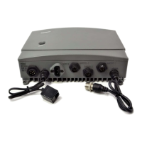
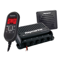
Ray55E Rear Connections
The ends of all wires are clipped at the factory so that no bare metal is exposed.
You must strip back the insulation before installation. If you are not connecting a
wire or set of wires (SPEAKER, for example), leave them insulated. If you have
stripped back a wire that you will not be connecting, clip the bare wire down to
the insulation.
Power
The red and black Power Cord provides connection to DC power. Slide the bullet
connectors on the cord into their mates (with the same colored wire) on the rear
of the radio. Connect the stripped wires on the Power Cord to the nearest primary
source of the boat's DC power. A suitable source would be a circuit breaker on the
power panel or a fuse block near the unit, rated at 10 amps. Connect the red wire
to the positive terminal of the power source and the black wire to the negative
(ground) of the power source. The red and black wires each contain an in-line fuse
rated at 10A, 250V, slow-blow. If the fuses ever need to be replaced, be sure to use
the same type and rating.
The power cord must be long enough to reach the DC power source. If additional
wire length is required, the cable can be extended by adding more cable as
necessary. However, for power cable runs longer than 15 feet, larger wire
diameter size should be used to prevent voltage line loss. To ensure adequate
current draw to the equipment, Raymarine recommends that you use lugs to
connect the power cable to the DC supply and that the lug connections be both
crimped and soldered.
Antenna
Power
NMEA / Speaker
fuses
RayMic /
Mic Relocation
Ground
D10333-2
 Loading...